

1
Safety precautions
Be sure to read this Instruction Manual and appended documents thoroughly before installing, operating the inverter.
Maintenance and service items in this manual are only caution related items. Read QRG (Quick Reference Guide) carefully before starting the
maintenance and service. (QRG can be downloaded from our website.)
In the Instruction Manual, safety instructions are classified into two levels, namely WARNING and CAUTION.
: Indicates that incorrect handling may cause hazardous situations, which may result in serious personal injury or death.
: Indicates that incorrect handling may cause hazardous situations, which may result in moderate or slight personal injury or
physical damage alone.
Note that even a level situation may lead to a serious consequence according to circumstances. Be sure to follow every safety
instruction, which contains important safety information. Also focus on and observe the items and instructions described under "Notes" in the text.
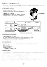
1. Installation
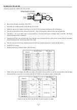
2. Wiring
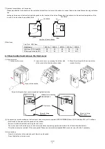
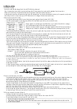
Make sure that the voltage of AC power supply matches the rated voltage of your inverter. Otherwise, you run the risk of injury or fire.
- Do not input single-phase power into the 3-phase inverter. Otherwise, you run the risk of fire.
- Do not connect AC power supply to any of the output terminals (U, V, and W). Otherwise, you run the risk of injury or fire.
- NE-S1 series inverter do not have terminals for braking resistor. Do not connect the resistor. Otherwise there is a risk of fire.
- Connect an earth-leakage breaker to the power input circuit. Otherwise, you run the risk of fire.
- Use only the power cables, earth-leakage breaker, and magnetic contactors that have the specified capacity (ratings). Otherwise, you run the risk
of fire.
- Do not use the magnetic contactor installed on the primary and secondary sides of the inverter to stop its operation.
- Tighten each screw to the specified torque. No screws must be left loose. Otherwise, you run the risk of fire.
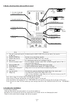
- Before operating slide switch in the inverter, be sure to turn off the power supply. Otherwise, you run the risk of electric shock and injury.
- Please make sure that earth or ground screw is tighten properly and completely.
- First, check the screws of output terminal (U, V and W) are properly tighten, and then tighten the screws of input terminal (R,S and T)
Basic Manual of Hitachi NE-S1 series inverter
Thank you for purchasing the Hitachi NE-S1 series inverter.
Please read this document and QRG(Quick Reference Guide), and understand perfectly how to handle
properly and the safety cautions of the product before operation, for safety and proper usage.
Note that this Manual is intended for each product and should be delivered to the end user of the inverter.
NT341BX
Many of the drawings in the Instruction Manual show the inverter with covers and/or parts blocking your view being removed.
Do not operate the inverter in the status shown in those drawings. If you have removed the covers and/or parts, be sure to reinstall them in their
original positions before starting operation, and follow all instructions in the Instruction Manual when operating the inverter.
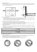
- Install the inverter on a non-flammable surface, e.g., metal. Otherwise, you run the risk of fire.
- Do not place flammable materials near the installed inverter. Otherwise, you run the risk of fire.
- When carrying the inverter, do not hold its top cover. Otherwise, you run the risk of injury and damage by dropping the inverter.
- Prevent foreign matter (e.g., cut pieces of wire, sputtering welding materials, iron chips, wire, and dust) from entering the inverter. Otherwise, you
run the risk of fire.
- Install the inverter on a structure able to bear the weight specified in the Instruction Manual. Otherwise, you run the risk of injury due to the inverter
falling.
- Install the inverter on a vertical wall that is free of vibrations. Otherwise, you run the risk of injury due to the inverter falling.
- Do not install and operate the inverter if it is damaged or its parts are missing. Otherwise, you run the risk of injury.
- Install the inverter in a well-ventilated indoor site not exposed to direct sunlight. Avoid places where the inverter is exposed to high temperature,
high humidity, condensation, dust, explosive gases, corrosive gases, flammable gases, grinding fluid mist, or salt water. Otherwise, you run the risk
of fire.
- The inverter is precision equipment. Do not allow it to fall or be subject to high impacts, step on it, or place a heavy load on it. Doing so may cause
the inverter to fail.
- Be sure to ground the inverter. Otherwise, you run the risk of electric shock or fire.
- Commit wiring work to a qualified electrician. Otherwise, you run the risk of electric shock or fire.
- Before wiring, make sure that the power supply is off. Otherwise, you run the risk of electric shock or fire.
- Perform wiring only after installing the inverter. Otherwise, you run the risk of electric shock or injury.
- The inverter must be powered OFF before you change any of the slide switch settings.Otherwise, you run the risk of electric shock or injury.
CAUTION
WARNING
CAUTION
WARNING
CAUTION
CAUTION
CAUTION


