background image


9


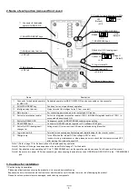
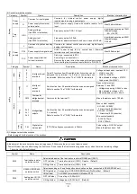
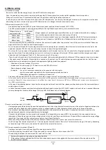
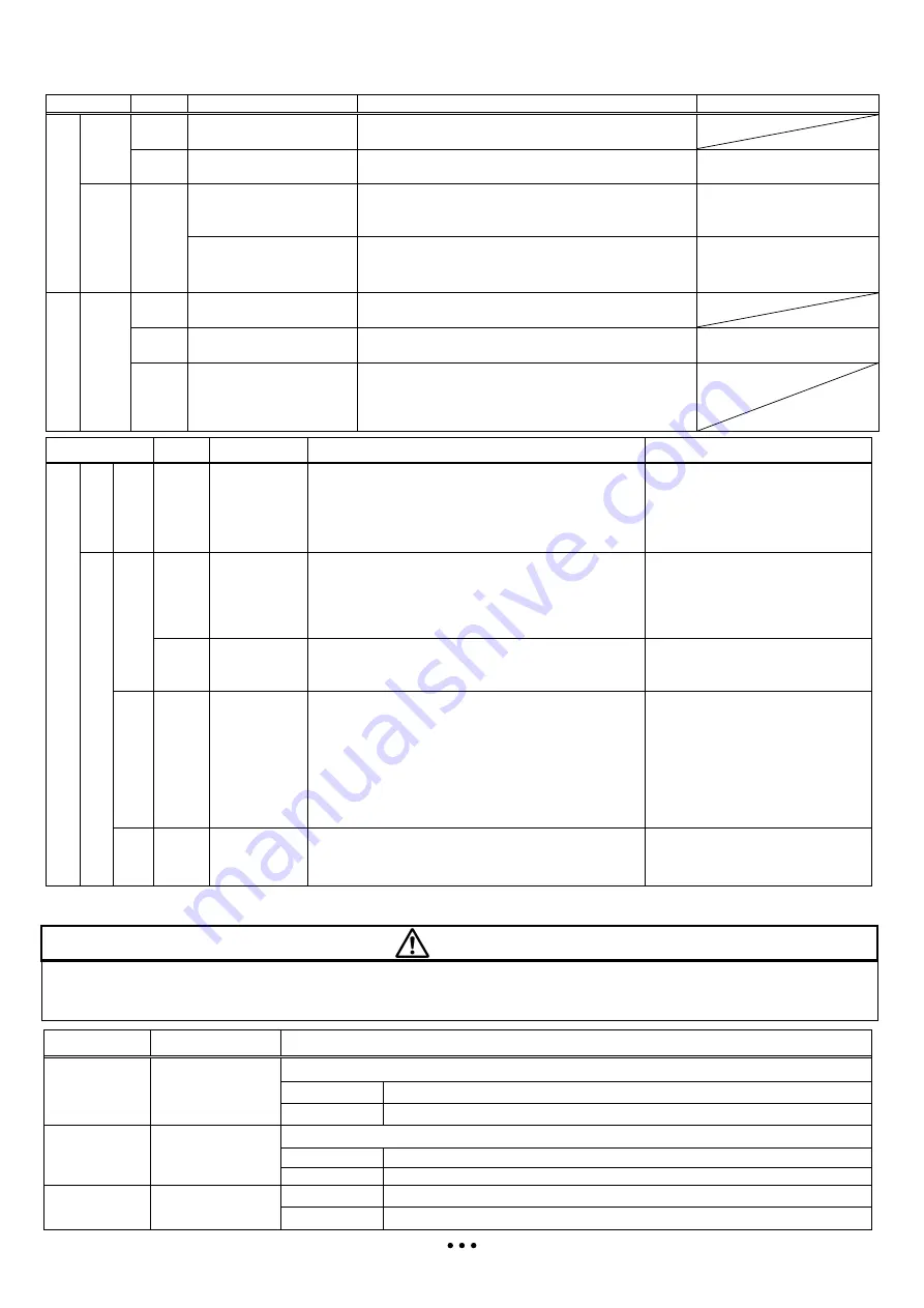
(2) Control terminal description 

Category 

Symbol 

Name 

Description 

Electrical characteristics 


Power 
supply 

Common for input signals 

Common  for  internal  control  power  supply,  digital 

inputs/outputs, analog inputs/outputs 


Power supply for external 
potentiometer 

DC10V  power  supply.  Used  with  variable  resistor  for  O 

input. 

Max.10mA withdraw 

A

n

a

lo

g


Freq. 
set 

O/OI 

Analog voltage 
(Use SW6 for selection) 

Frequency set via DC0~10V input 

Input impedance=apprx.10k


Allowable range; 

-0.3~+12VDC 

Analog current 
(Use SW6 for selection) 

Frequency set via 0~20mA 
Parameter adjustment should be done in case of 4~20mA 

Input impedance=apprx.250


Allowable range; 
0~24mA 

D

ig

ita

Power 
supply 

Common of digital and analog 
Inputs 

Common  for  internal  control  power  supply,  digital  inputs, 

analog inputs/outputs 


P24 

Power supply for digital inputs 

DC24V  power  supply  for  dry  contact  input.  (Common 

terminal in case of source logic) 

Max.100mA output 

PLC 

Power supply terminal   
for input terminals 

Sink logic : connected to P24 
Source logic : connected to L 
Remove the jumper wire when using external power supply 

for controlling the dry contact inputs (Refer to “QRG”5.7) 


Category 

Symbol 

Name 

Description 

Electrical characteristics 

D

ig

ita

In

p

u

C

o

n

ta

c


Intelligent input 
terminals 

Select 5 functions from 35 available functions when can be 
assigned to  any  terminal  1 to  5. Sink  or source  logic can 
be selected. Refer to section 7.3 of “QRG” for the details 

Voltage between each input and PLC 

- V(ON) = min.18V 
- V(OFF) = MAX.3V 
- Max. allowable voltage = 27VDC 
- Load current 5mA (24V) 

O

u

tp

u

O

p

e

n

-c

o

lle

c

to

11 


Intelligent 
output 
terminals 

One function from 28 available functions can be assigned. 
Refer to section 7.3 of “QRG” for the details 

Open collector output 
Between 11 and CM2 

- Voltage drop during ON=4V or less 
- Max. allowable voltage = 27V 
- Max allowable current = 50mA 

CM2 

Common for 
intelligent output 
terminals 

Common for the terminal 11. 

Max. allowable current = 100mA 
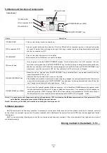
R

e

la

y


AL0 
AL1 
AL2 

Intelligent relay 
outputs 

One function from 28 available functions can be assigned. 
(1-c contact) 
Refer to section 7.3 of “QRG” for the details. 

Max. contact capacity 

AL1-AL0 : AC250V, 

2A(resistive),0.2A(inductive) 

AL2-AL0 : AC250V, 

1A(resistive),0.2A(inductive) 

Min. contact capacity 

AC100V, 10mA 
DC5V, 100mA 

P

u

ls

e


tr

a

in


FM 

Digital pulse 
train output 

(PTO) Pulse frequency maximum is 3.6kHz 

Pulse voltage : DC0/10V output 
Max. allowable current : 2mA 

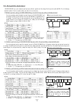
(3) Changeover switch description 

Refer to page 5 for the location of the switches. 


Symbol 

Name 

Description 

SW4 

Termination resistor 

selection switch 

Select able/disable of the termination resistor of RS485 port (RJ45) 

OFF (left side) 

Termination resistor (100

)


Disable    (Default) 

ON (right side) 

Termination resistor (100

)


Able 

SW5 

RS485/OPE(RS422) 

selection switch 

Select depending on the options and communication method, connected to RS422/RS485 port.   

OFF(right side)    For operator (OPE-S/SR/SBK/SRmini),ProDriveNext    (Default) 

ON(left side) 

For RS485 communication (Modbus-RTU) 

SW6 

Analog input (O/OI)   

selection switch 

OFF (left side) 

Current input (0~20mA) OI 

ON (right side) 

Voltage input (0~10Vdc) O    (Default) 

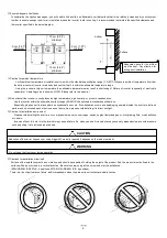
- Adjustment of the switch must be done during power off. Otherwise there is a risk of electric shock. 

- Power ON must be done after closing the front cover. Do not open the front cover during power up, or when there is a remaining voltage. 

There is a risk of electric shock.


     CAUTION

CAUTION

CAUTION

CAUTION    

Summary of Contents for NES1-OP

Page 1: ...nd QRG Quick Reference Guide and understand perfectly how to handle properly and the safety cautions of the product before operation for safety and proper usage Note that this Manual is intended for each product and should be delivered to the end user of the inverter NT341BX Many of the drawings in the Instruction Manual show the inverter with covers and or parts blocking your view being removed D...

Page 2: ...cility can be operated Otherwise you run the risk of injury or damage to the machine controlled by the inverter Do not touch the heat sink which heats up during the inverter operation Otherwise you run the risk of burn injury The inverter allows you to easily control the speed of motor or machine operations Before operating the inverter confirm the capacity and ratings of the motor or machine cont...

Page 3: ...tection required at end application h Use 60 75ºC CU wire only i Tightening torque and wire range as shown in the table below Model No Required Torque N m Wire Range AWG NES1 002S 0 8 1 0 16 14 NES1 004S 0 8 1 0 16 14 NES1 007S 1 8 14 12 NES1 015S 1 8 12 10 NES1 022S 1 8 10 NES1 002L 0 8 1 0 16 14 NES1 004L 0 8 1 0 16 14 NES1 007L 0 8 1 0 16 14 NES1 015L 1 8 14 NES1 022L 1 8 12 j Distribution fuse...

Page 4: ... name of the inverter 2 Manufacturing number 3 When you bought the product 4 Contents of your inquiry Damaged portion and condition and else 1 4 Warranty Terms The warranty period under normal installation and handling conditions shall be two 2 years from the date of manufacture or one 1 year from the date of installation whichever occurs first The warranty shall cover the repair or replacement at...

Page 5: ...lease be sure to check that this lamp is turned OFF after waiting 10 minutes of power OFF Note1 Refer to page 13 for the description of the display and key operation Note 2 Position of charge lamp depends on the model Refer to page 11 for the details Note 3 Pay attention when operating by PC via RS422 RS485 port as the operation can also be done from the panel of the inverter Note 4 Be sure to tur...

Page 6: ...g is generated inside the inverter electronic parts are short circuited each other to cause a failure Also please avoid installing it in direct sunlight Caution for installation environment Please avoid installing the inverter in such places where dust corrosive gas explosive gas flammable gas mist of grinding fluid or salt pollution etc exists Invasion of dust dirt etc into the inverter may cause...

Page 7: ...C software ProDriveNext See above for the position of the window Be sure to make window after removing the front cover There are cutouts at the window so it can be removed easily by pressing up side and bottom side of the window alternatively The window cannot be restored if it is once opened Please use commercially supplied RJ45 connector cap or the like if necessary 3 How to attach Press the fro...

Page 8: ... G Earth terminal To make grounding Be sure to make this grounding to avoid electric shock and for improving the EMC performance The terminal is located on the heatsink Intelligent inputs 7 terminals 0 10VDC 10bit PLC P24 DC24V L P H O OI Category D grounding 200V class DC10V 5 2 1 3 4 Intelligent input terminal 11 CM2 Relay contacts AL0 AL1 AL2 L DC10V 10mA Max 4 7kΩ 4 7kΩ L FM L Pulse train outp...

Page 9: ...gent output terminals One function from 28 available functions can be assigned Refer to section 7 3 of QRG for the details Open collector output Between 11 and CM2 Voltage drop during ON 4V or less Max allowable voltage 27V Max allowable current 50mA CM2 Commonfor intelligent output terminals Common for the terminal 11 Max allowable current 100mA Relay AL0 AL1 AL2 Intelligent relay outputs One fun...

Page 10: ... An inverter run by a private power generator may overheat the generator or suffer from a deformed output voltage waveform of the generator Generally the generator capacity should be five times that of the inverter kVA in a PWM control system or six times greater in a PAM control system In the case of important equipment to shorten the non operational time of inverter failure please provide a back...

Page 11: ...AWG14 2 0 M3 5 7 6 1 0 EX30 10A H10C 10A 0 75 007SB AWG14 2 0 M4 10 1 4 EX30 15A H10C 15A 1 5 015SB AWG10 5 5 M4 10 1 4 EX30 20A H20 20A 2 2 022SB AWG10 5 5 M4 10 1 4 EX30 20A H20 30A 3 phase 200V 0 2 002LB AWG16 1 25 M3 5 7 6 1 0 EX30 5A H10C 10A 0 4 004LB AWG16 1 25 M3 5 7 6 1 0 EX30 10A H10C 10A 0 75 007LB AWG16 1 25 M3 5 7 6 1 0 EX30 10A H10C 15A 1 5 015LB AWG14 2 0 M4 10 1 4 EX30 15A H10C 15A...

Page 12: ...for each operator for the detailed information 3 5 line LCD operator WOP WOP having serial number of 16918938000081 or later 2011 07 production is applied to NE S1 series inverter English only WOP can be used with connector cable ICS 1 3 and connected to the RS422 RS485 port RJ45 in the inverter Turn the changeover switch to the operator side OFF side in that case See page 9 Refer to the manual fo...

Page 13: ...red up with pressing the RUN STOP RESET key and keep it pressing 5seconds and take off from the key Changeover switch must be changed later on Note 1 RS422 RS485 port RJ45 This is a port for external operator Modbus connection or ProDrioveNext RS485 operator changeover switch must be operated before Power ON In case of Modbus communication it is necessary to set the changeover switch and parameter...

Page 14: ...meters as needed Function Name Code Setting Range Note Acceleration time F002 0 00 to 3600 sec default 10 sec Deceleration time F003 0 00 to 3600 sec default 10 sec One of the following is required when changing default parameters on NE S1 series inverters Dedicated operator NES1 OP Digital operator 5 line LCD operator Modbus PC programming tool ProDriveNext 3 Method to perform driving in FW RV te...

Page 15: ...al input signal 3 wire input possible Modbus Option Operator Dedicated Operator Intelligent input terminal 5terminals Analog input 1terminal O OI terminal Voltage input10bit 0 to 10V Current input 10bit 0 to 20mA selected with a selection switch Output signal Intelligent output terminal 5 open collector output terminals 1 relay 1 from c contact output terminal Pulse Output 1terminal connection RS ...

Page 16: ...use applicable to the products NEVER USE THE PRODUCTS FOR AN APPLICATION INVOLVING SERIOUS RISK TO LIFE OR PROPERTY WITHOUT ENSURING THAT THE SYSTEM AS A WHOLE HAS BEEN DESIGNED TO ADDRESS THE RISKS AND THAT THE HITACHI INDUSTRIAL EQUIPMENT SYSTEMS PRODUCTS ARE PROPERLY RATED AND INSTALLED FOR THE INTENDED USE WITHIN THE OVERALL EQUIPMENT OR SYSTEM See also product catalogs Model W mm H mm D mm D1...

Reviews: