-25-
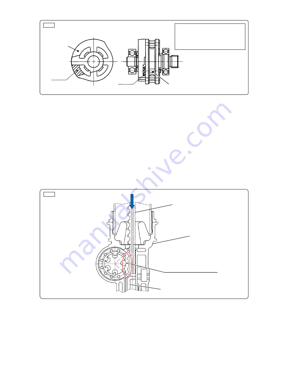
Fig. 30
Fig. 31
• Remove dust from between the Pin Wheel
[27](27)
and Needle Roller D3
[30](30)
and apply about 1.5 g
of Molub-Alloy 777-1 grease to the Needle Roller D3
[30](30)
, eight Needle Rollers D4
[32](32)
, and
Needle Roller D4.5
[26](26)
evenly.
• Apply about 0.2 g of Isoflex Topas NB52 grease to the two Slide Rings
[13](13)
included in the brand-new
Piston Ass'y
[15](15)
evenly. Then mount the two Slide Rings
[13](13)
to the Piston Ass'y
[15](15)
.
• Apply about 1.0 g of Isoflex Topas NB52 grease to the X-ring
[14](14)
included in the brand-new Piston
Ass'y
[15](15)
evenly. Then mount the X-ring
[14](14)
to the Piston Ass'y
[15](15)
.
• Put the Pin Wheel
[27](27)
in the Nose
[17](17)
. Facing the notch of the Pin Wheel
[27](27)
to Blade
Guide (A)
[70](70)
, push the Piston Ass'y
[15](15)
down to the bottom dead point without meshing with
the eight Needle Rollers D4
[32](32)
and Needle Roller D4.5
[26](26)
as shown in Fig. 31. Apply about
1.5 g of Isoflex Topas NB52 grease to the inside of the Cylinder
[5](5)
evenly.
NOTE: If the Position Detector [25](25) is not precisely located, an error (causing the orange LED
of the battery indicator to blink) may occur.
• Slowly tighten the four Nylock Bolts M6
[11](11)
to fasten the Chamber Base
[10](10)
and Chamber Cover
[4](4)
. Be careful not to pinch and damage the O-ring (I.D 94.5)
[7](7)
.
• Perform reassembly of the power assembly according to pages 16 to 20.
Pay special attention to the position of
the Position Detector
[25](25)
.
If the Position Detector
[25](25)
is
misaligned, the standby position of the
piston is also misaligned. (See page 29.)
[27](27)
[25](25)
Notch
Notch
Notch of the Pin Wheel
[27](27)
[15](15)
[17](17)
[70](70)


