--- 29 ---
10-2. Disassembly and Reassembly of the Output Section
(1) Piston [12], Cylinder [17] and related parts
Tool required:
Hexagon bar wrench (5 mm)
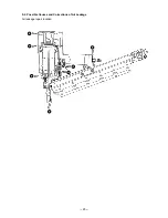
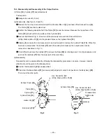
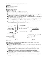
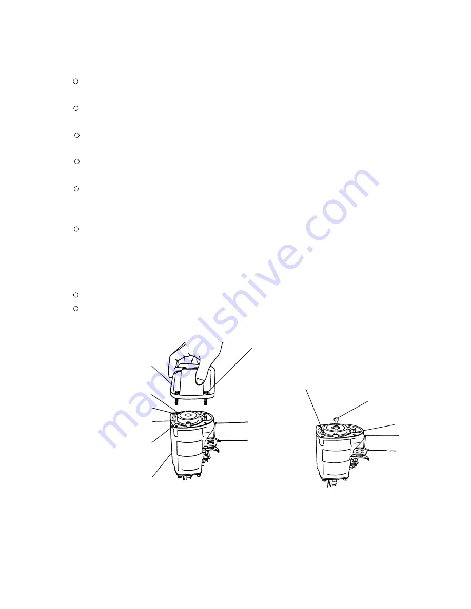
(a) Disassembly (See Figs. 8, 9 and 10.)
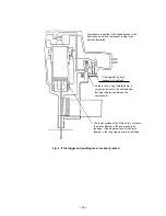
Remove the four Hex. Socket Hd. Bolts (W/Sp. Washer) M6 x 25 [3], and take off the Exhaust Cover [4].
The Piston [12] can then be taken out.
Perform the following operation first if the Piston [12] cannot be removed because the top surface of the
Piston [12] is flush with the top surface of the Cylinder [17].
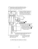
Next, as illustrated in Fig. 9, screw two of the previously removed Hex. Socket Hd. Bolts
(W/Sp. Washer) M6 x 25 [3] into the provided holes on the Cylinder Plate [15].
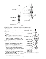
Gripping these two bolts, simultaneously turn and pull upward to remove the Cylinder Plate [15]. When this
has been accomplished, the Cylinder [17] and other parts which make up the output section can be
removed, as illustrated in Fig. 10.
If it is difficult to remove the Cylinder [17], remove the Nose [32] by referring para. 10-2-(3) procedures, and
push out the Cylinder [17] from the lower part of the main body.
(b) Reassembly
Reassembly can be accomplished by following the disassembly procedures in reverse. However, special
attention should be given to the following items.
Confirm that Gasket (G) [23] is reassembled.
Check that the Base Washer [21] is securely and properly mounted to its position in the Body Ass'y [25].
Then mount the other parts.
Fig. 9
Fig. 8
Exhaust Cover [4]
Piston [12]
Gasket (B) [5]
Cylinder Plate [15]
Cylinder [17]
Body Ass'y [25]
Hex. Socket Hd. Bolt
(W/Sp. Washer) M6 x 25 [3]
Cylinder Plate [15]
Threaded hole
for M6 bolts
Hex. Socket Hd. Bolt
(W/Sp. Washer) M6 x 25 [3]
Summary of Contents for NR 83A2
Page 46: ......

