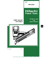


Summary of Contents for NR 83AA3
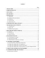
Page 45: ......
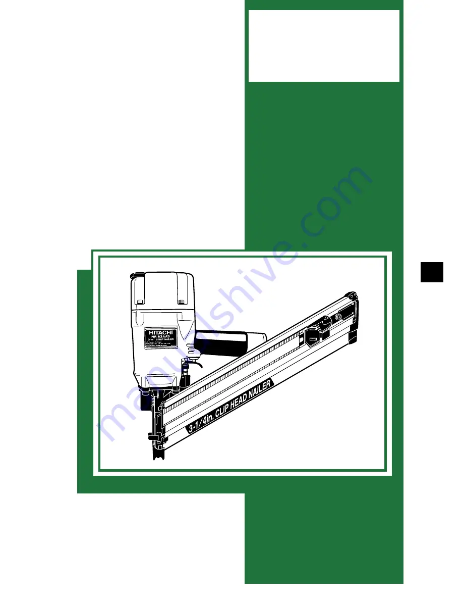
The Hitachi NR 83AA3, a robust and reliable framing nailer, is a powerful tool designed to handle heavy-duty construction projects with ease. To ensure optimal performance and maintenance, don't forget to consult the Technical Data And Service Manual, available for free download at our website. Get the most out of your tool with this comprehensive manual from 88.208.23.73:8080.
Page 45: ......