--- 29 ---
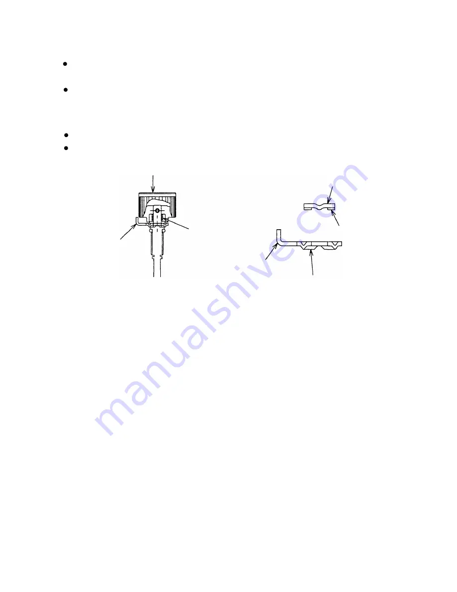
(2) Disassembly and reassembly of the adjuster unit
(a) Disassembly (See Fig. 22.)
Remove the Retaining Ring (E-type) for D3 Shaft [61]. Then Pushing Lever (A) [35] and the adjuster unit can
be separated.
Pull out the Roll Pin D2 x 16 [55]. Then the adjuster unit can be disassembled.
(b) Reassembly
Disassembly procedures should be followed in the reverse order. Note the following points.
Mount Adjuster Plate (A) [58] facing its bent portion toward the Adjuster [54].
Mount Adjuster Plate (C) [57] facing its convex portion toward Adjuster Plate (A) [58].
Fig. 22
Adjuster [54]
Convex portion
Bent portion
Adjuster Plate (C) [57]
Adjuster Spring [56]
Bent portion
Adjuster Plate (A) [58]
Summary of Contents for NR 90AD (S)
Page 42: ......


