English
13
䡬
Keep away from ignition sources. No smoking.
䡬
Clear the area of children or unauthorized personnel.
䡬
Do not store the tool, fuel cell and battery in a cold
weather environment. Keep the tool, fuel cell and
battery in a warm area until beginning the work.
䡬
If the tool, fuel cell and battery are already cold, bring
it in a warm area and allow the tool to warm up before
use.
Observe temperature limit of max. 50°C (120°F).
Do not expose to an open flame and sparks!
䡬
This tool may not drive completely below when;
– at low temperature fuel cell loose the required
propellant force,
– at high temperature fuel cell overdose.
䡬
Do not use the tool in the rain or where excessive
moisture is present.
䡬
This tool is not recommended for use at altitudes
above 1500 m (5000 feet), or in temperature below
0°C (30°F).
1. Fuel cell
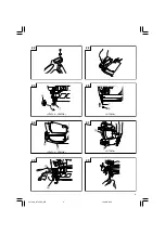
To attach the metering valve to a fuel cell:
(1) Separate the metering valve and the cap from the gas
cartridge (See
Fig. 3
(1)).
(2) Press forward (stem side) and downward on the front
side of the metering valve (See
Fig. 3
(2)).
(3) Press downward on the rear of the metering valve
until it seals (See
Fig. 3
(3)).
Check the metering valve:
Press the metering valve stem on fuel cell two or three
times against a stationary object and release.
If gas is not dispersed, fuel cell is empty. Replace it.
Observe Safety Regulations
CAUTION
䡬
If the gas leaks from the metering valve or the gas
cartridge after attached the metering valve, replace
with the new metering valve.
䡬
Do not attempt to reuse the metering valve.
Replace with the new metering valve.
2. Battery
You must charge the battery before use.
The charging method of battery is shown in page 12.
3. Check on safety
CAUTION
䡬
Unauthorized persons (including children) must be
kept away from the equipment.
䡬
Wear eye protector.
䡬
Check the retaining screws which fix the top cover,
etc. for tightness.
Check the tool for defective or rusty parts.
䡬
Check whether or not the push lever works correctly
without nails, fuel cell and battery. Also check whether
or not any dirt has adhered to the moving parts of the
push lever.
䡬
Recheck on operational safety.
BEFORE USE
1. Insert battery into the tool (See Fig. 4)
Do not operate the push lever or trigger while
installing the battery.
Make sure the battery indicator light is flashing GREEN
(See
Fig. 5
).
If the battery indicator light is flashing RED, the battery
doesn’t have enough power and it needs to be
charged.
BATTERY INDICATOR LIGHT
–
Flashing GREEN: Enough power remaining (The
light turns steady during
operation).
–
Flashing RED: Insufficient power remaining (The
light turns steady during operation).
–
OFF: The battery is extremely empty. Charge the
battery.
2. Insert fuel cell into the tool
(1) Push up and pull out the actuater (See
Fig. 6
).
(2) Insert the fuel cell into the tool (See
Fig. 7
).
(3) Insert the stem of fuel cell into the hole of adaptor
(See
Fig. 8
).
(4) Close the actuater (
Fig. 9
).
3. Load nails
CAUTIONS
䡬
When loading nails into Nailer,
(1) do not depress trigger;
(2) do not depress push lever; and
(3) keep your face, hands feet and other body parts,
as well as those of other persons away from the
nose muzzle to avoid possible injury during usage
and carrying.
<NT65GS • NT65GB>
(1) Insert nail strip into rear of magazine (See
Fig. 10
).
(2) Slide the nail strip forward in the magazine (See
Fig. 11
).
(3) Push the nail feeder (A) to engage the nail feeder (B)
to the nail strip (See
Fig. 12
).
NOTE
䡬
Use nail strip of more than 10 nails.
The Nailer is now ready to operate.
Removing the nails:
1
Pull the nail feeder (B) backward (See
Fig. 13
).
2
Return the nail feeder (B) forward quietly while
pushing the nail feeder (A).
3
Pull out nails from the back of the magazine (See
Fig.
14
).
<NT50GS>
(1) Lightly press the stop lever and gently pull out the
magazine cover. (See
Fig. 15
)
(2) Set nail strip into the magazine and keep the points
of nails in contact with groove. (See
Fig. 16
)
(3) Slide the nail strip into the blade guide. (See
Fig. 17
)
(4) Confirm that nail strip is placed with side guide
grooves and groove properly, then push the magazine
cover forward to be latched.
NOTE
䡬
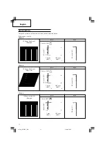
The nails shown in page 11 can be loaded onto the
side guide groove of the magazine without any
adjustment.
Always keep the points of nails in contact with Groove.
01Eng_NT65GS_WE
12/3/08, 8:45
13
Summary of Contents for NT 65GB
Page 94: ...93 NT65GS 08Back_NT65GS_WE 12 3 08 8 49 93 ...
Page 96: ...95 NT65GB 08Back_NT65GS_WE 12 3 08 8 49 95 ...
Page 98: ...97 NT50GS 08Back_NT65GS_WE 12 3 08 8 49 97 ...
Page 100: ...99 08Back_NT65GS_WE 12 3 08 8 49 99 ...
Page 101: ...100 08Back_NT65GS_WE 12 3 08 8 49 100 ...


