background image

--- 12 ---

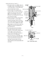
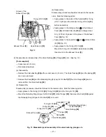
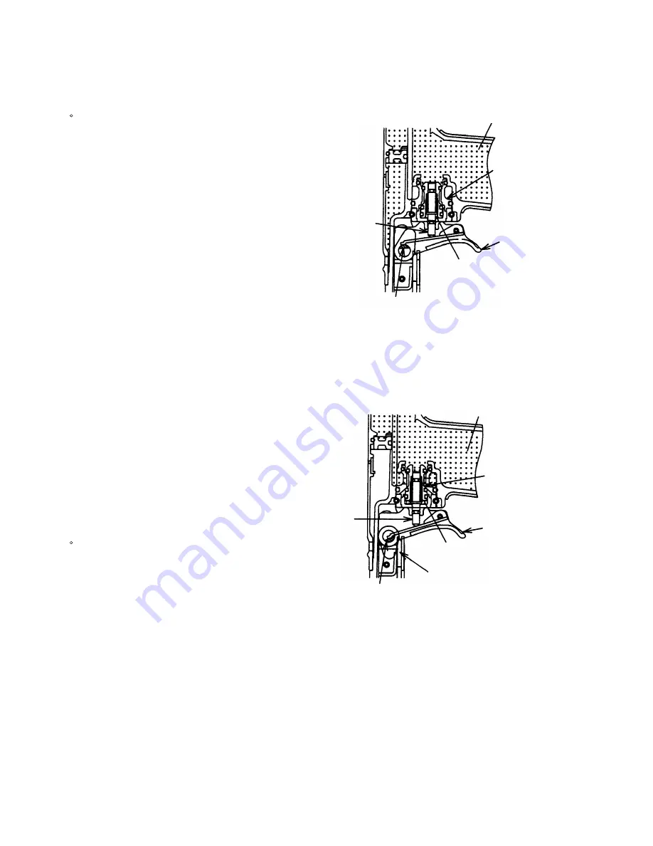
(4) Single actuation mechanism/contact actuation mechanism: (Fig. 8 and Fig. 9)

Single/contact actuation mechanism changeover is accomplished by turning the switching device

(Change Knob (C) 

[58]

).

Single actuation mechanism (Switching device:

upward position):

1) Immediately after driving the first nail, the

control valve should be as shown in Fig. 7.

2) When only Pushing Lever (B) 

[40]

 is released

and Trigger (C) Ass'y 

[36]

 is held as shown in

Fig. 8, the plate of Trigger (C) Ass'y 

[36]

contacts Change Knob (C) 

[58]

 and the Plunger

[67]

 returns (lowers) only halfway.

Because of this, compressed air does not flow

into the valve piston lower chamber, and Valve

Piston 

[63]

 remains in the lowered position.

Accordingly, the Piston 

[12]

 remains in the

lowered position as shown in Fig. 6.

3) When Trigger (C) Ass'y 

[36] 

is released, the

Plunger

 [67]

 returns (lowers) completely as

shown in Fig. 5.  Compressed air then flows into

the valve piston lower chamber, and the Valve

Piston 

[63]

 is forced upward.  The Piston 

[12]

then returns fully upward.  Therefore, unless

Trigger (C) Ass'y 

[36]

 is released after each

nailing operation, the structural mechanism

prevents the next nailing operation.

Contact actuation mechanism (Switching device:

downward position):

1) Immediately after the first nail is driven, the

control valve should be as shown in Fig. 7.

2) Even when only Pushing Lever (B) 

[40]

 is

released and Trigger (C) Ass'y 

[36]

 is held, the

Plunger 

[67]

 returns (lowers) completely as

shown in Fig. 9.  Thus the Piston 

[12]

 returns

(raises) fully.  Accordingly, continuous nailing

can be accomplished by pushing only Pushing

Lever (B) 

[40]

 up and down while holding

Trigger (C) Ass'y 

[36]

 depressed.

Plunger 

[67]

Valve piston
lower chamber

Trigger (C)
Ass'y 

[36]

Valve Piston 

[63]

Accumulator

Switching device (Change Knob (C) 

[58]

)

(Upward position)

Fig. 8  Single actuation mechanism

Plunger 

[67]

Pushing Lever (B) 

[40]

Valve portion
lower chamber

Trigger (C) Ass'y 

[36]

Valve Piston 

[63]

Accumulator

Switching device (Change Knob (C) 

[58]

)

(Downward position)

Fig. 9  Contact actuation mechanism

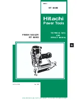
Summary of Contents for NT 65M2

Page 1: ...TECHNICAL DATA AND SERVICE MANUAL FINISH NAILER NT 65M2 SPECIFICATIONS AND PARTS ARE SUBJECT TO CHANGE FOR IMPROVEMENT LIST No E032 Dec 2005 N MODEL NT 65M2 Hitachi Power Tools ...

Page 2: ...ERVICE MANUAL a symbol s is are used in the place of company name s and model name s of our competitor s The symbol s utilized here is are as follows Symbols Utilized Competitors Company Name Model Name Porter Cable FN250B P Bostitch SB 1664FN Q ...

Page 3: ...ion Principle 10 9 TROUBLESHOOTING GUIDE 13 9 1 Troubleshooting and Correction 13 9 2 Regrinding the Driver Blade 16 9 3 Possible Causes and Countermeasures for Air Leakage 17 10 DISASSEMBLY AND REASSEMBLY 19 10 1 General Precautions in Disassembly and Reassembly 19 10 2 Disassembly and Reassembly of the Output Section 20 10 3 Disassembly and Reassembly of the Control Valve Section 22 10 4 Disasse...

Page 4: ...el Model NR 90AD 3 APPLICATIONS Finish nailing of door casings and similar frame assemblies Fastening of drawer bottoms and similar assembly work in the construction of various cabinets and cases 4 SELLING POINTS 360û adjustable exhaust Tool less depth adjustment Capable of cleaning chips and saw dust of course it drives nails thanks to the blow nozzle With single actuation contact actuation selec...

Page 5: ... lubricant 4 oz oil feeder Code No 872042 Pneumatic tool lubricant 1 oz oil feeder Code No 876212 Grease ATTOLUB No 2 500 g 1 1 lbs Code No 317918 5 SPECIFICATIONS 5 1 Specifications Reciprocating piston type Model Driving system NT 65M2 Operating pressure 5 8 5 kgf cm2 gauge pressure 70 to 120 psi 5 2 Nail Selection The Model NT 65M2 utilizes small head T shaped nails finish nails collated by adh...

Page 6: ...INGLE SEQUENTIAL ACTUATION MECHANISM First press the pushing lever against the wood next pull the trigger to drive the nail First pull the trigger next press the pushing lever against the wood to drive the nail After nailing once nailing will not be possible again until the trigger is released and pressed again CONTACT ACTUATION MECHANISM First press the pushing lever against the wood next pull th...

Page 7: ...he nail to be fully driven For example when driving a 65 mm 2 1 2 nail into a hard wood workpiece with the Model NT 65M2 a pressure of about 5 5 kgf cm2 78 psi 5 4 bar allows the nailer to drive the nail flush with the surface A pressure beyond this value causes the nail head to be driven below the wood surface Figure 2 should be used as a reference only because those values vary depending on the ...

Page 8: ...x 2 9 in 299 x 272 x 74 mm 0 039 ft 3 cycle 1 1 ltr cycle 100 nails Top loading 1 8 kg 4 0 lbs Provided P Blow nozzle Provided Provided None Direction change of exhaust air Handing grip Applicable nails 16 Ga finish Length Dia Provided Rubber 0 054 0 065 in 1 4 1 65 mm Provided Rubber 1 2 1 2 in 25 65 mm Rubber 3 4 2 1 2 in 19 65 mm 0 054 0 065 in 1 4 1 65 mm None 5 8 5 kgf cm 2 70 120 psi 11 9 x ...

Page 9: ...g Instructions to enhance the safe efficient use of the tool by the customer Salespersons must be thoroughly familiar with the contents of the Handling Instructions to be able to offer appropriate guidance to the customers during sales promotion 7 2 Warning Label Each Model NT 65M2 unit is provided with a Warning Label illustrated below which lists basic safety precautions in its use Carefully ens...

Page 10: ...sted in the Handling Instructions provided with each unit While there are no specific safety regulations there are related items in various general safety regulations with which the salespersons should be familiar in order to properly advise the customer Please check your national and or local regulations for applicable items Some applicable items are outlined below The U S A OSHA 1926 102 Eye and...

Page 11: ...ght saving 2 The internal structure of the exhaust cover is common to the Model NT 65MA2 3 The air duster section is common to the Model NT 65MA2 2 Control section Common to the Model NR 90AD 3 Driving section Most of parts have been newly designed 1 The adjuster is common to the model NT 65MA2 2 Pushing lever A is the same as the Model NT 65MA2 4 Magazine section Most of parts have been newly des...

Page 12: ...gazine section Grip Rubber A 45 Driving section Output section Exhaust vent Valve Bushing B 60 Control valve section Valve Piston 63 Switching device Change Knob C 58 Plunger 67 Trigger C Ass y 36 Cylinder Ring 17 Cylinder Plate 16 O ring S 10 25 O ring 1AP 3 24 Spring 21 Valve Packing 20 Valve Bushing 26 O ring S 3 23 Plunger 22 Blow nozzle section Accumulator Plunger Spring 65 Valve Bushing A 68...

Page 13: ...e exhaust valve 2 When the exhaust valve opens the compressed air in the head valve chamber is discharged into the atmosphere through the air passage 3 When the air pressure on the bottom surface of Head Valve A 10 overcomes the strength of the Head Valve Spring 8 Head Valve A 10 is pushed upward At this time Head Valve A 10 seals with the Exhaust Cover 5 blocking the passage to the exhaust vent 4...

Page 14: ...ealed and at the same time Head Valve A 10 and the Exhaust Cover 5 separate to open the exhaust vent 4 The compressed air above the Piston 12 is discharged into the atmosphere through the exhaust vent In this way the air pressure above the Piston 12 is reduced and the greater pressure of the air accumulated in the return air chamber pushes the Piston 12 upward 5 If the air pressure below the Pisto...

Page 15: ...valve piston lower chamber and the Valve Piston 63 is forced upward The Piston 12 then returns fully upward Therefore unless Trigger C Ass y 36 is released after each nailing operation the structural mechanism prevents the next nailing operation Contact actuation mechanism Switching device downward position 1 Immediately after the first nail is driven the control valve should be as shown in Fig 7 ...

Page 16: ... fragments and apply oil to the nail feeder ribbon spring and the nail rail Magazine is loaded with abnormal nails bent nails large or small head nails abnormal collation etc Magazines A and B are abnormal deformed or damaged Nail feeder is abnormal deformed or damaged Ribbon sping is abnormal deformed or damaged Magazine cover is abnormal deformed damaged or fatigued Check the nail feeding sectio...

Page 17: ...Control valve section Cylinder s internal surface is abnormal deposits of dirt or worn Repair or replace Apply grease O ring is worn or oiling is needed Apply grease or replace Disassemble the control valve and check the O ring 2 Nails are bent when being driven See item 1 Unspecified nails are used For short nails the adjuster is raised too high Do not use unspecified workpiece Nails are not full...

Page 18: ... blade Replace the defective part 3 Head of a nail driven into a workpiece protrudes from the wood surface Turn the adjuster to the lowest position and drive a nail Drive a nail into soft wood workpiece and check if the head protrudes from the nose tip Operate the nailer without nails and check if the driver blade is projected from the nose cap Disassemble the output section and check the piston O...

Page 19: ...hould be ground as shown in Fig 10 To grind with a grinder gradually grind the tip while cooling the ground area with water to prevent it from being excessively heated Excessive grinding will rapidly reduce the service life of the driver blade Driver blade Fig 10 7 û ...

Page 20: ... is worn or deformed The O ring I D 20 8 9 is abnormal worn deformed or damaged Head Valve A 10 is abnormal worn deformed or damaged A Exhaust port Air leakage point Possible cause When control valve OFF B Exhaust cover When control valve ON Head Valve A 10 is abnormal a portion is worn deformed or broken The Exhaust Cover 5 is abnormal a portion is deformed or clogged with dust The Hex Socket Hd ...

Page 21: ...f the Valve Piston 63 is abnormal worn broken or flawed The O ring P 18 61 of Valve Bushing B 60 is abnormal broken or flawed The internal surface g of the valve cavity of the Body Ass y 31 is abnormal E Control valve 1 The upper O ring P 7 62 of the Valve Piston 63 is abnormal worn broken or flawed The Feed Piston O ring I D 14 59 of Valve Bushing B 60 is abnormal broken or flawed The internal su...

Page 22: ...ssembly Apply grease ATTOLUB No 2 Code No 317918 to the O rings and O rings sliding portions When installing the O rings be careful not to damage the O rings and prevent dirt entry Oil required Hitachi pneumatic tool lubricant 30 cc 1 oz oil feeder Code No 877153 120 cc 4 oz oil feeder Code No 874042 1 ltr 1 quart can Code No 876212 If the Gasket 6 is damaged replace it and check that no air is le...

Page 23: ... Piston Bumper 18 with the Bumper Sheet 19 assembled etc can be removed Remove the Hex Socket Hd Bolt M6 x 12 1 with a hex bar wrench 5 mm The Plate 2 and the Top Cover 3 can now be removed Hex Socket Hd Bolt M6 x 12 1 Head Bumper 7 Gasket 6 Exhaust Cover 5 Hex Socket Hd Bolt W Sp Washer M5 x 25 4 Top Cover 3 Plate 2 Head Valve A 10 O ring I D 20 8 9 Head Valve Spring 8 Piston 12 O ring I D 31 7 1...

Page 24: ...grease to the lip portions b and c of Head Valve A 10 Fig 12 Apply grease to the O ring I D 20 8 9 Mount the O ring I D 20 8 9 to Head Valve A 10 then mount it to the Exhaust Cover 5 2 Disassembly and reassembly of the Valve Bushing 26 Plunger 22 etc See Fig 13 Tools required Socket wrench 14 mm Flat blade screwdriver a Disassembly Remove the Valve Bushing 26 with a socket wrench 14 mm The Valve P...

Page 25: ...shing Lever Guide 38 and Trigger C Ass y 36 can be removed Fig 14 Disassembly and reassembly of the control valve section Trigger C Ass y 36 Roll Pin D3 x 30 55 Pushing Lever Guide 38 Trigger Arm C 35 Body Ass y 31 Change Knob C 58 Retaining Ring E type for D6 Shaft 30 O ring P 7 62 Valve Bushing A 68 Plunger Spring 65 Valve Piston 63 Valve Bushing B 60 O ring P 18 61 Feed Piston O ring I D 14 59 ...

Page 26: ...t to damage the Valve Piston 63 Valve Bushing A 68 Valve Bushing B 60 etc Do not pul out the end of the Plunger 67 with the pliers 3 To take out Valve Bushing B 60 put a 1 5 to 3 mm 0 059 to 0 118 dia wire with its end hooked into the hole in the bushing and pull it out while being careful not to damage the internal surface of Valve Bushing B 60 as shown in Fig 16 Valve Bushing B 60 Be careful not...

Page 27: ...nit will be aligned with the roll pin holes in the Body Ass y 31 First insert the roll pin puller 3 mm dia into the roll pin holes Then upon confirming that the puller passes through the hole drive in the Roll Pins D3 x 25 53 and D3 x 32 54 If an attempt is made to drive the roll pin with force when the roll pin grooves in Valve Bushings A 68 and B 60 are not aligned with the roll pin holes in the...

Page 28: ...ssembly of the driving section a Disassembly Continuously turn the Adjuster 42 in the direction in which the nail is raised when adjusting the driving depth refer to ADJUSTING THE NAILING DEPTH on page 21 in the Instruction Manual so that Pushing Lever A 43 can be removed Remove the Hex Socket Hd Bolt M5 x 20 51 with the hex bar wrench 4 mm and remove the two Hex Socket Hd Bolt W Sp Washer M5 x 25...

Page 29: ...uide 74 Guide Plate A 75 and Guide Plate B 73 flush with the Body Ass y 31 After assembly check that Pushing Lever A 43 Pushing Lever B 40 and the Adjuster 42 move smoothly 10 5 Disassembly and Reassembly of the Cap and the Magazine Section 1 Disassembly and reassembly of the cap See Fig 19 Tool required Hex bar wrench 4 mm Fig 19 Disassembly and reassembly of the cap Gap A 47 Hex Socket Hd Bolt M...

Page 30: ...ot pulled during the above operation Remove the retaining ring for D3 shaft with the blade of a screwdriver Then the ribbon spring can be removed Pull out the Roll pin D2 5 x 12 98 with the roll pin puller 3 mm 118 dia and remove the Hex Socket Hd Bolt M4 x 16 100 with the hex bar wrench M4 Then the Magazine Protector 99 Sleeve 88 and nail rail can be removed Remove the Hex Socket Hd Bolt W Sp Was...

Page 31: ...to the deepest position Set Change Knob C 58 to single actuation single sequential actuation see 5 2 Check that the Model NT 65M2 operates by pressing Pushing Lever A 43 against a test piece first then pulling Trigger C Ass y 36 Check that the Piston 12 is still showing from the Blade Guide 74 tip outlet of nails after Pushing Lever A 43 is released from the test piece with Trigger C Ass y 36 pull...

Page 32: ...ow Top Cover Exhaust Cover Gasket Head Valve Spring O ring Head Valve A 60 min 50 Guide Plate B Guide Plate A Blade Guide Magazine A Magazine B Magazine Cover Nail Feeder Nail Rail Pushing Lever B Pushing Lever Spring Adjuster Pushing Lever A General Assembly Adjustment Cylinder Body Valve Cylinder Cylinder Plate O ring x 2 Piston Bumper Bumper Sheet Cylinder Ring Body Ass y Knob Plunger O ring x ...

Page 33: ... 69 69 501 502 29 1 2 3 4 5 6 7 8 9 10 11 12 13 14 15 16 17 18 19 20 21 22 23 24 25 26 27 28 31 30 32 34 35 36 37 38 39 40 41 42 43 44 45 46 47 48 49 50 51 52 53 54 56 57 58 59 60 61 62 63 62 64 65 66 67 66 68 85 86 69 70 71 72 73 74 75 76 77 80 78 79 81 82 83 87 90 91 90 92 93 94 95 96 97 98 99 100 101 55 88 84 ...

Page 34: ... 333 PLUNGER 1 23 881 715 O RING S3 1 24 873 093 O RING 1AP 3 1 25 987 105 O RING S 10 1 26 882 701 VALVE BUSHING 1 27 968 643 RETAINING RING E TYPE FOR D4 SHAFT 1 28 884 334 KNOB 1 29 CAUTION PLATE 1 30 955 479 RETAINING RING E TYPE FOR D6 SHAFT 1 31 885 662 BODY ASS Y 1 INCLUD 45 32 NAME PLATE 1 33 NAME PLATE B 1 34 885 675 PROTECTOR 1 35 885 689 TRIGGER ARM C 1 36 885 657 TRIGGER C ASS Y 1 INCL...

Page 35: ...T W SP WASHER M5X25 2 73 885 635 GUIDE PLATE B 1 74 885 636 BLADE GUIDE 1 75 885 634 GUIDE PLATE A 1 76 884 323 LOCK LEVER 1 77 949 685 ROLL PIN D3X20 10 PCS 1 78 885 656 PIN 1 79 885 655 RIBBON SPRING 1 80 949 770 ROLL PIN D4X14 10 PCS 1 81 885 641 MAGAZINE A 1 82 885 652 HEX SOCKET HD BOLT W SP WASHER M5X12 1 83 872 971 RETAINING RING E TYPE FOR D3 SHAFT 1 84 877 371 NYLON NUT M5 1 85 885 659 HA...

Page 36: ...SSORIES ITEM NO CODE NO DESCRIPTION REMARKS NO USED STANDARD ACCESSORIES ITEM NO CODE NO DESCRIPTION REMARKS NO USED NT 65M2 Printed in Japan 051115N 501 885 549 SAFETY GLASSES 1 502 885 676 CASE 1 601 881 768 GRIP TAPE A 1 602 880 407 TAPE 2 ...

Page 37: ......
Reviews: