background image

* ALTERNATIVE PARTS

--- 2 ---

ITEM

NO.

CODE NO.

DESCRIPTION

REMARKS

NO.

USED

PARTS

1 -- 05

NV 50AF3

1

949-819

HEX. SOCKET HD. BOLT M5X10 (10 PCS.)

1

2

944-260

WASHER

1

3

881-841

TOP COVER

1

4

881-840

HEAD RING

1

5

881-835

MUFFLER

1

*

6

881-838

PROTECTOR (A)

1

*

6

881-883

PROTECTOR (A)

1

FOR H/V

7

949-757

HEX. SOCKET HD. BOLT M5X20 (10 PCS.)

4

*

8

881-879

EXHAUST COVER

1

*

8

881-865

EXHAUST COVER

1

FOR H/V

9

881-839

GASKET (A)

1

10

881-851

HEAD VALVE SPRING

1

11

877-699

HEAD VALVE O-RING (I.D 16.8)

2

12

881-837

HEAD VALVE (A)

1

13

881-834

PISTON RING

1

14

881-833

PISTON O-RING

1

15

881-832

PISTON

1

16

990-067

O-RING (1AS-50)

1

17

881-831

CYLINDER PLATE

1

18

984-483

O-RING (S-36)

1

19

881-864

CYLINDER O-RING

1

20

881-829

CYLINDER

1

21

881-830

PISTON BUMPER

1

*

22

881-877

BODY ASS’Y

1

INCLUD. 43, 44

*

22

881-878

BODY ASS’Y

1

INCLUD. 43, 44 FOR H/V

23

955-479

RETAINING RING (E-TYPE) FOR D6 SHAFT

1

24

875-638

O-RING (S-12)

1

25

880-674

TRIGGER (A)

1

26

881-846

ADJUSTER SHAFT

1

27

881-847

LATCH

1

28

316-389

PUSHING LEVER GUIDE

1

29

881-882

SPRING

1

30

881-843

PUSHING LEVER (B)

1

31

881-811

NAIL GUIDE SHAFT

1

32

873-093

O-RING (1AP-3)

1

33

881-810

NOSE

1

34

949-660

HEX. SOCKET HD. BOLT M6X20 (10 PCS.)

2

35

983-545

NEEDLE ROLLER

1

36

949-770

ROLL PIN D4X14 (10 PCS.)

1

37

878-132

FEEDER ARM

1

38

878-340

FEEDER SPRING

1

39

881-818

FEEDER

1

40

881-819

PUSHING LEVER (A)

1

41

881-092

NOSE CAP (A)

1

42

877-371

NYLON NUT M5

1

43

880-408

GRIP TAPE

1

44

880-407

TAPE

2

45

880-183

O-RING (I.D 37.2)

1

*

46

880-379

CAP

1

*

46

882-162

CAP

1

FOR H/V

47

872-035

DUST CAP

1

Summary of Contents for NV 50AF3

Page 1: ...TECHNICAL DATA AND SERVICE MANUAL COIL NAILER NV 50AF3 SPECIFICATIONS AND PARTS ARE SUBJECT TO CHANGE FOR IMPROVEMENT LIST No E019 Jan 2005 N MODEL NV 50AF3 Hitachi Power Tools ...

Page 2: ... Mechanism 10 7 2 Operation Principle 12 8 TROUBLESHOOTING 14 8 1 Troubleshooting and Correction 14 8 2 Possible Causes and Corrections for Air Leakage 19 9 DISASSEMBLY AND REASSEMBLY 21 9 1 General Precautions in Disassembly and Reassembly 21 9 2 Disassembly and Reassembly of the Output Section 22 9 3 Disassembly and Reassembly of the Control Valve Section 24 9 4 Disassembly and Reassembly of the...

Page 3: ... materials such as plywood or drywall Fastening of a variety of interior finishing materials Nailing of a variety of architectural metals such as reinforcing brackets 0 35 m 0 014 or less in thickness for joining frames or rafters of wooden buildings 4 SELLING POINTS Newly designed magazine for easy nail top loading with tilt bottom Continuous nailing single nailing changeover capability For Europ...

Page 4: ... proper level for the driving resistance of the nails can shorten the service life of the coil nailer Be sure to instruct customers to adjust both the air pressure level and the adjuster dial by referring to the table below Adjust the adjuster dial and the air pressure level referring to the table below Perform a test driving When the nail head is sunk below the wood surface adjust the adjuster di...

Page 5: ...Height x Width Standard accessories Optional accessories NV50AF3 Reciprocating piston type 4 9 8 3 bar 5 8 5 kgf cm2 70 120 psi Gauge pressure 3 pcs sec 1 4 kg 3 1 lbs 252 mm x 269 mm x 112 mm 9 15 16 x 10 19 32 x 4 13 32 Reciprocating piston type 0 80 liter cycle at 6 9 bar 0 80 liter cycle at 7 kgf cm2 0 28 ft3 cycle at 100 psi 3 8 NPT thread Corrugated cardboard box Sleeve type 310 mm x 350 mm ...

Page 6: ...to use genuine HITACHI nails to ensure satisfactory driving quality CAUTION Ensure that nails are as specified in Figs 1 2 and 3 Other nails will cause clogging of nails and subsequent damage to the nailer NOTE Aluminum nails may bend when driven into a hard workpiece Test before use 4 6 mm 0 181 4 8 mm 0 189 2 3 mm 0 091 1 8 mm 0 071 27 mm 1 1 16 50 mm 2 Sheet collated nails Min Max 4 6 mm 0 181 ...

Page 7: ... 071 0 091 24 0 98 22 0 866 100 3 937 72 2 835 0 6 0 024 Fig 2 Dimensions of wire collated nails Fig 3 Dimensions of sheet collated nails 4 5 0 177 0 8 0 031 12 5 0 492 9 7 0 382 14 0 551 6 0 236 6 0 236 L 25 45 1 1 3 4 d D1 D2 H 1 6 2 0 0 063 0 079 25 1 98 3 858 47 1 85 ...

Page 8: ...g wire collated nails of 2 1 mm dia x 50 mm length 0 080 dia x 2 length into Hemlock below a 12 mm plywood sheet with the Model NV 50AF3 a force of about 5 3 bar 5 6 kgf cm2 79 8 psi is required to drive the nail flush with the surface of the plywood If the nail is driven with a force more than 5 5 bar 5 6 kgf cm2 79 8 psi the nail head will be sunk below the wood surface Please use Fig 4 as a rou...

Page 9: ...omers who want to use it Salespersons must instruct the customers to read the Handling Instructions attached to the sequential fire parts set and also the Handling Instructions of the Model NV 50AF3 thoroughly for correct use 4 5 6 7 8 4 5 6 7 8 60 70 80 90 100 110 120 Air pressure setting to drive nail flush with NV50AF3 Nail d x L mm x mm d L 2 3 mm x 50 mm 0 091 x 2 bar kgf cm2 PSi 2 1 mm x 50 ...

Page 10: ...ales promotion 2 Warning Label Each Model NV 50AF3 unit is provided with a Warning Label illustrated below which lists basic safety precautions in its use Carefully ensure that the customer fully understands and follows these precautions before using the tool GEFAHR Vor Gebrauch die BETRIEBSANLEITUNG LESEN Ein Nichtbeachten der Betriebsanleitung KANN ZU ERNSTHAFTEN VERLETZUNGEN FÜHREN Anwender und...

Page 11: ...tions in Sales Promotion The salespersons must instruct customers to observe the following precautions 1 An air pressure less than 4 4 bar 4 5 kgf cm2 63 psi or more than 7 8 bar 8 kgf cm2 112 psi can affect the performance service life and safety of the Model NV 50AF3 Pay special attention to the pressure level capacity and piping of the air compressor If using an air compressor capable of high a...

Page 12: ...he parts have been newly designed though the basic construction is the same as that of the Model NV 38AB2 The muffler has been added to reduce air exhaust force Control valve section This section is common to that of the Model NV 38AB2 Driving section The adjuster nose nail guide and other parts have been newly designed for improvement of operability in nailing depth adjustment Magazine section Mo...

Page 13: ...e ass y Feeder Feed claw Nail guide Feed piston Nail holder Magazine cover Guide lock A Fig 5 Construction Cross section A A Exhaust port Head ring Muffler Protector A Piston Driver blade Body Feeder Feed chuck Adjuster Nose Ejection port Vinyl cover Dust proof cover Magazine Hook Valve piston B Change knob B Trigger A Magazine section Output section Driving section ...

Page 14: ...rough air passage A 3 The air pressure applied against the lower surface of the head valve soon exceeds the force of the head valve spring and pushes the head valve up The head valve is pushed fully upward by the compressed air and seals the upper surface of the exhaust cover and the head valve 4 When the head valve is pushed up the compressed air flows rapidly into the cylinder and pushes down th...

Page 15: ... the cylinder is opened to the atmosphere 2 When the head valve seals the upper surface of the cylinder the compressed air accumulated in the return air chamber passes through air passage C presses on the lower surface of the piston and forces the piston to return upward to its original position Also the compressed air above the piston is exhausted through the head valve hole 3 The compressed air ...

Page 16: ...th proper nails Nail feeding section nose feeder feed piston etc The sliding resistance of the feed piston is too great The nail guide face of the nose is abnormal deformed jagged damaged and or worn The feed spring and or feeder spring is abnormal damaged and or fatigued The feeder is abnormal damaged and or worn Remove the feed piston and examine the feed piston slide surface of the nose Apply g...

Page 17: ...ed parts and replace parts Adjust the height of the nail holder correctly Magazine section Pushing lever A Magazine Check whether or not a nail catches on another nail in the magazine Check whether or not a nail catches on some part of the magazine Check the nail holder for the height Correct or replace parts Output section Piston driver blade etc Air pressure is low Adjust air pressure in the ran...

Page 18: ...en bent The wood being nailed is very hard Check whether or not the nail is bent even when it is driven into soft wood The nailer cannot be used because the material is beyond its applicable range 3 Nails cannot be driven into the wood completely the heads cannot be made flush The adjuster is incorrectly set Try to drive nails with the adjuster set to maximum depth Adjust the adjuster to the optim...

Page 19: ...g position Wire collation nails Wire collated nails are deformed Deformation in collation angle collation pitch etc The diameter of nail head is too small Wire collation nails whose head diameter is 4 3 mm 0 17 or less are liable to cause jamming Check whether or not nails approved by Hitachi are used Check nails referring to the following figures Use the nails approved by Hitachi Remove abnormal ...

Page 20: ... foreign matter in the feed piston chamber Body Nail feeding is incomplete The feeder is worn and the sliding section is abnormal The nail guide face of the nose and the sliding section of the feeder are abnormal deformed warped and or damaged The nail guide face of the nail guide is worn The driver blade head is worn The feed spring and the feeder spring are abnormal damaged fatigued and or damag...

Page 21: ...E g h G F Cross section A A Air leakage portion A Exhaust port Cause When the trigger is turned off When the trigger is turned on Abnormality in Head Valve A 12 and the Cylinder 20 Wear and deformation of the sealed face of the b section Abnormality in the Head Valve O ring I D 16 8 11 or wear deformation and or breakage of Head Valve A 12 Abnormality damage in the Exhaust Cover 8 Abnormality in H...

Page 22: ...on of driver blade abnormality in sealed faces The deformation of the face f of the Body Ass y 22 Abnormality wear deformation breakage and or scratches in the O Ring S 12 24 E Feed piston F Control valve 1 Abnormality wear breakage and or scratches in the O ring P 18 73 of the Feed Piston 72 or wear and or deformation of the Nose 33 on the sliding face Abnormality wear breakage and or scratches i...

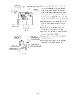
Page 23: ...S No 2 Code No 939536 to the O rings and the O ring sliding area When installing the O rings exercise care to avoid scratches and dust Lubricants required Hitachi pneumatic tool lubricant 1 oz 30 cc Oil feeder Code No 877153 4 oz 120 cc Oil feeder Code No 874042 1 quart 1 liter Can Code No 876212 Replace gasket A if broken and make sure that there is no air leak after installation Exercise care to...

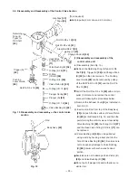
Page 24: ... as the Piston 15 the Cylinder 20 and the Piston Bumper 21 can be removed b Reassembly Proceed in reverse to the disassembly procedure while taking care to observe the following procedures Apply Shell Tonna Oil S32 to the Piston Ring 13 the Piston O Ring 14 and the inside of the Cylinder 20 Apply grease to the O Ring S 36 18 and the Cylinder O Ring 19 and then install them Mount the Cylinder Plate...

Page 25: ...ing it Fig 14 Apply Shell Tonna Oil S32 to the inside of the Cylinder 20 and mount the Cylinder 20 Mount Gasket A 9 so that its hole matches the blowhole of the Body Ass y 22 Apply grease to the O Ring 1AS 50 16 and its sealing surface and mount it Fit the convex portion of the Exhaust Cover 8 in the concave portion of the Top Cover 3 Head Valve Spring 10 Head Valve O Ring I D 16 8 11 A Fig 13 Exh...

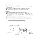
Page 26: ...control valve unit excluding Valve Bushing B 56 the O ring S 18 57 and the Head Valve O ring I D 16 8 11 can be removed iii Valve Bushing B 56 can be pulled out using a wire by hooking a bent end into the hole of Valve Bushing B 56 Exercise care not to cause any damage to Valve Bushing B 56 interior with such a wire hooked portion Exercise care not to damage Valve Piston B 60 and Valve Bushing B 5...

Page 27: ...n Fig 18 First insert a roll pin puller 3 mm dia and hammer in the Roll Pin D3 x 18 50 after making sure that it can pass through the roll pin hole If the roll pin is hammered in with the roll pin groove of Valve Bushing A 65 out of alignment with the roll pin hole at the Body Ass y 22 the circumferential area of Valve Bushing A 65 may be damaged resulting in difficulty of reassembly and disassemb...

Page 28: ...fore adhering them to the Body Ass y 22 First adhere the end of the Grip Tape 43 near the roll pin hole of the Body Ass y 22 and start to wind it around the Body Ass y 22 When the winding is completed fix both wound ends of the Grip Tape 43 with the Tape 44 Fig 19 Be careful that the Grip Tape 43 and the Tape 44 cannot be peeled off once they are adhered Tape 44 Grip Tape 43 Wound end of the Grip ...

Page 29: ...ng it with a wrench b Reassembly Proceed in reverse to the disassembly procedure with lubricant applied to the O ring I D 37 2 45 Fig 20 Disassembly and reassembly of the cap and the magazine section Nylon Nut M5 42 Cap 46 Pin 81 Pin 81 Protector B 79 Feeder Shaft Ring 82 O Ring I D 37 2 45 Hook 48 Machine Screw W Washers M5 x 30 49 Magazine 83 Feeder Shaft Ring 82 Holder Cap A 85 Magazine Cover 8...

Page 30: ... 5 mm dia Then the Nail Holder 87 the Holder Shaft 89 and the Spring 90 can be removed b Reassembly Proceed in reverse to the disassembly procedure taking care of the following points Check that the Spring 90 is inserted between the concave portion of the Magazine 83 and the convex portion of the Holder Shaft 89 Then insert the Pin 81 when mounting the Holder Shaft 89 to the Magazine 83 Fig 21 Che...

Page 31: ... Bolts M6 x 20 34 Then the Nose 33 and Pushing Lever A 40 can be removed Body Ass y 22 O Ring S 12 24 Adjuster Shaft 26 Bolt Washer M4 66 Roll Pin D1 6 x 12 68 Adjuster Knob 69 Pushing Lever Guide 28 Bumper 75 Spring 74 O Ring P 18 73 Feed Piston 72 O Ring P 9 71 Latch 27 Spring 29 Pushing Lever B 30 Adjuster 70 Nose 33 Hex Socket Hd Bolt M6 x 20 34 Needle Roller 35 Roll Pin D4 x 14 36 Feeder Arm ...

Page 32: ...e Adjuster Spring 67 the Bolt Washer M4 66 the Latch 27 the Adjuster Shaft 26 the Spring 29 Pushing Lever B 30 and the Adjuster 70 can be removed b Reassembly Proceed in reverse to the disassembly procedure taking care of the following points Align the dihedral width portion and the radius portion of the Latch 27 to the window of Pushing Lever B 30 when reassembling Fig 24 Mount the Adjuster 70 an...

Page 33: ...he feed piston chamber may make the movement of the Feed Piston 72 dull Carefully clean with a clean rag before reassembly Lubricate the O Ring P 9 71 and the O Ring P 18 73 before reassembly Move the O Ring P 18 73 of the Feed Piston 72 toward right and fill the channel with lubricant Apply grease to the O ring sliding surfaces of the Feed Piston 72 and the Nose 33 before reassembly though too mu...

Page 34: ...e to the disassembly procedure taking care of the following points Carefully remove any dust stuck in the Nail Guide 96 before reassembly Degrease the Nail Guide 96 screw before tightening the Nylock Hex Socket Hd Bolt M4 x 10 104 After reassembly push Nail Stopper A 97 and Nail Stopper B 99 with a finger and make sure that they quickly return to position Mount the Nail Guide Shaft 31 facing the c...

Page 35: ...brought into operation by a simple pull on Trigger A 25 and by light pressure on Pushing Lever A 40 The Feed Piston 72 reliably operates with an air pressure of 4 9 bar 5 kgf cm2 70 psi Open the Nail Guide and perform a nailing operation with no nail being fed Nails do not jam and are not bent when nailed with an air pressure of 4 9 bar 5 kgf cm2 70 psi Note Perform test nailing with the Adjuster ...

Page 36: ... Valve O ring O Ring x 6 Valve Piston B Plunger Spring Plunger A Valve Bushing A Adjustment Cylinder Body and Valve Body Ass y Feed Piston O Ring x 2 Spring Bumper Feed Piston Cover Piston Piston O Ring Piston Ring Change Knob B Spring C Feeder Arm Feeder Spring Feeder Cylinder O Ring x 3 Cylinder Plate Cylinder O ring Piston Bumper Nose Magazine Ass y Magazine Cover Nail Holder Guide Lock Nail Gu...

Page 37: ...2 13 14 15 16 17 18 19 20 21 22 23 24 25 26 27 28 29 30 31 32 33 34 35 36 37 38 39 40 41 42 43 44 45 46 47 48 49 50 51 52 53 54 11 56 57 58 59 60 61 62 63 64 65 66 67 68 69 50 70 71 72 73 74 75 76 77 78 79 81 82 81 82 83 84 85 86 87 88 89 90 93 94 95 96 97 98 99 105 501 502 503 504 505 506 507 55 80 91 92 100 101 102 103 104 ...

Page 38: ...881 864 CYLINDER O RING 1 20 881 829 CYLINDER 1 21 881 830 PISTON BUMPER 1 22 881 877 BODY ASS Y 1 INCLUD 43 44 22 881 878 BODY ASS Y 1 INCLUD 43 44 FOR H V 23 955 479 RETAINING RING E TYPE FOR D6 SHAFT 1 24 875 638 O RING S 12 1 25 880 674 TRIGGER A 1 26 881 846 ADJUSTER SHAFT 1 27 881 847 LATCH 1 28 316 389 PUSHING LEVER GUIDE 1 29 881 882 SPRING 1 30 881 843 PUSHING LEVER B 1 31 881 811 NAIL GU...

Page 39: ...DJUSTER SPRING 1 68 878 222 ROLL PIN D1 6X12 1 69 881 848 ADJUSTER KNOB 1 70 881 845 ADJUSTER 1 71 872 645 O RING P 9 1 72 880 168 FEED PISTON 1 73 873 570 O RING P 18 1 74 880 409 SPRING 1 75 877 476 BUMPER 1 76 880 170 FEED PISTON COVER 1 77 983 748 RETAINING RING FOR D24 HOLE 1 78 880 177 MAGAZINE BUSHING 1 79 881 850 PROTECTOR B 1 80 878 183 WARNING LABEL 1 EXCEPT FOR H V 81 881 825 PIN 2 82 8...

Page 40: ...100 880 393 SPRING 1 101 881 815 NAIL GUIDE COVER 1 102 881 816 COVER 1 103 878 337 SLEEVE B 1 104 880 413 NYLOCK HEX SOCKET HD BOLT M4X10 1 105 881 820 MAGAZINE ASS Y 1 INCLUD 81 90 501 944 459 HEX BAR WRENCH 5MM 1 502 944 458 HEX BAR WRENCH 4MM 1 503 943 277 HEX BAR WRENCH 3MM 1 504 881 093 NOSE CAP B 1 505 877 153 PNEUMATIC TOOL LUBRICANT 30CC 1 506 875 769 SAFETY GLASSES 1 507 881 849 CASE 1 5...

Page 41: ......

Reviews: