--- 26 ---
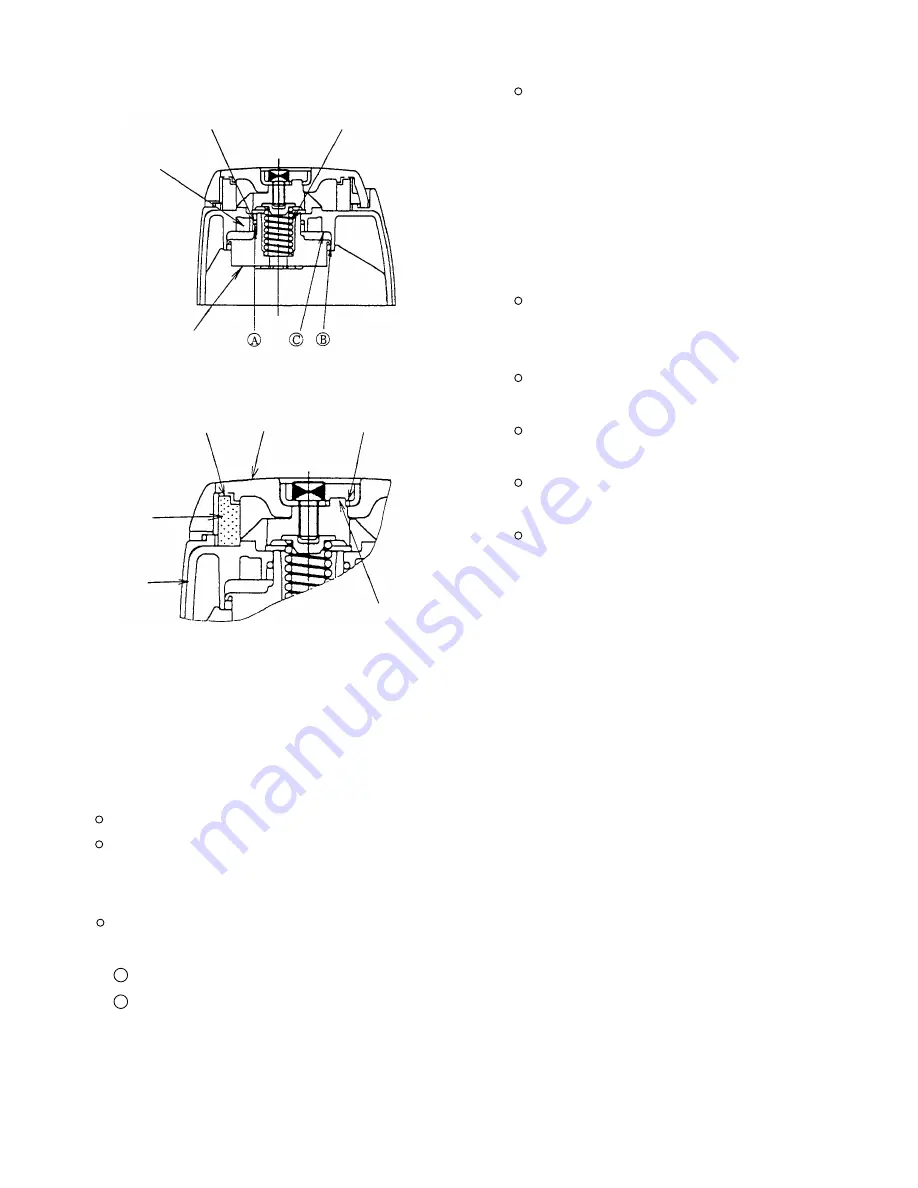
Protrusion of the
Exhaust Cover [7]
Protrusion of the
Muffler [4]
Top Cover [3]
Muffler [4]
Fig. 16
Exhaust
Cover [7]
Push Head Valve (A) [12] in the Exhaust
Cover [7] together with O-ring (P-22) [11]
for easier mounting. Before mounting,
apply grease to the sliding portion (A) and
the lip portions (B) and (C) of Head Valve
(A) [12] and seal about 0.5 g of grease
into the groove of the Exhaust Cover [7]
(Fig. 15).
Apply SHELL TONNA S32 oil (standard
accessory) to the inside of the Cylinder
[17] before mounting.
Align the hole of Gasket (A) [8] with the air
hole of the Body [23].
Apply grease to the sealing surface and
O-ring (S-70) [13] before mounting.
Mount the Muffler [4] facing its protruded
side to the Top Cover [3] side.
Fit the protrusion of the Exhaust Cover [7]
in the groove of the Plate [2].
Groove of the
Exhaust Cover [7]
O-ring (P-22) [11]
Fig. 15
Head Valve Spring [10]
10-3. Disassembly and Reassembly of the Control Valve Section
[Tools required] Roll pin pullers (3 mm dia. and 2.5 mm dia.)
(a) Disassembly (Fig. 17)
Remove the Retaining Ring (E-type) for D4 Shaft [21] to remove the lock knob.
Pull out the two Roll Pins D3 x 28 [60] with the roll pin puller (3 mm dia.). Then the trigger unit can be
removed from the Pushing Lever Guide [47]. The trigger unit can be disassembled by removing the Roll Pin
D2.5 x 16 [44].
Pull out the Roll Pins D3 x 22 [59] and the Roll Pins D3 x 28 [60] with the roll pin puller (3 mm dia.). Remove
the control valve section in accordance with the following procedure.
1 Remove the Exhaust Cover [7] in accordance with the procedure of 2.2 (1) on the previous page.
2 Insert a thin rod into the Body [23] through the top hole and push the top surface of Valve Piston (B) [70]
as shown in Fig. 18. Then the parts forming the control valve section except Valve Bushing (B) [67], O-ring
(S-18) [68] and Head Valve O-ring (I.D 16.8) [66] can be taken out.
Head Valve (A) [12]
Groove of Plate [2]
Summary of Contents for NV 65AF3
Page 45: ......


