--- 24 ---
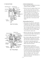
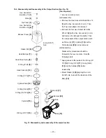
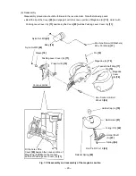
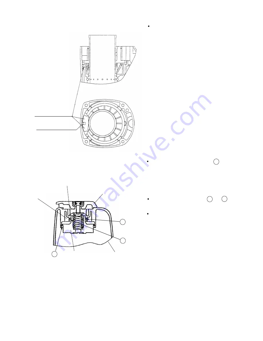
Top Cover [3]
Groove of the
Exhaust Cover [5]
O-Ring (P-22) [9]
Head Valve (A) [10]
Fig. 13
Exhaust Cover [5]
B
A
C
Apply grease to the sliding surface of
the Exhaust Cover [5] and Head Valve (A)
[10] and charge about 0.5 g (0.018 oz) of
grease in the groove of the Exhaust Cover
[5] (Fig. 13).
Apply grease to the lip portions and
of Head Valve (A) [10] (Fig. 21).
Apply grease to O-Ring (P-22) [9]. Mount
O-Ring (P-22) [9] to Head Valve (A) [10],
then mount it to the Exhaust Cover [5].
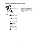
C
A
B
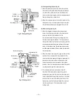
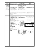
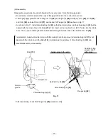
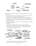
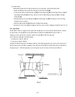
Mount the Cylinder Plate [12] to the
Cylinder [15] facing the stopper of the
Cylinder Plate [12] to the Piston Bumper
[20]. When mounting to the Body [18],
fit the rib of the Body [18] into the stopper
groove of the Cylinder Plate [12] (Figs. 11
and 12).
Fig. 12
Stopper of the
Cylinder Plate [12]
Rib of the Body [18]
Fig. 11
Summary of Contents for NV 75AG
Page 45: ......

