background image

COIL  NAILER

NV  83A2

LIST No. E007

Oct.  2002

POWER TOOLS

TECHNICAL  DATA

AND

SERVICE  MANUAL

SPECIFICATIONS  AND  PARTS  ARE  SUBJECT  TO  CHANGE  FOR  IMPROVEMENT

N

MODEL

NV  83A2

Summary of Contents for NV 83A2

Page 1: ...COIL NAILER NV 83A2 LIST No E007 Oct 2002 POWER TOOLS TECHNICAL DATA AND SERVICE MANUAL SPECIFICATIONS AND PARTS ARE SUBJECT TO CHANGE FOR IMPROVEMENT N MODEL NV 83A2 ...

Page 2: ...VICE MANUAL a symbol s is are used in the place of company name s and model name s of our competitor s The symbol s utilized here is are as follows Symbols Utilized Competitors Company Name Model Name SENCO SCN65 R PASLODE P350C Y BOSTITCH N80CB P ...

Page 3: ... Interchangeability of Parts 11 8 3 Operation Principle 13 9 TROUBLESHOOTING GUIDE 17 9 1 Troubleshooting and Correction 17 9 2 Possible Causes and Corrections of Air Leakage 22 10 DISASSEMBLY AND REASSEMBLY 25 10 1 General Precautions in Disassembly and Reassembly 25 10 2 Disassembly and Reassembly of the Output Section 26 10 3 Disassembly and Reassembly of the Control Valve Section 28 10 4 Disas...

Page 4: ...ition the Model NV 83A2 is equipped with a tool less nailing depth adjuster pop out magazine non slip rubber etc to meet the market demands Applicable nails are the same as those of the Model NV 83A The Model NV 83A2 weighs only 3 7 kg same as the Model NV 83A 3 APPLICATIONS Construction of wooden work such as floor and wall framing roof decking and subflooring Mobile and modular home construction...

Page 5: ...s equipped with a bottom loading magazine the Model NV 83A2 is equipped with the pop out magazine that allows easy nail loading from the top of the magazine thanks to the tilting nail holder The magazine can be opened closed just by the nail guide operation The Model NV 83A requires operation of both the nail guide and the latch at the rear of the magazine 4 Handle grip Thanks to the adoption of t...

Page 6: ...aging 396 mm x 143 mm x 366 mm 15 19 32 x 5 5 8 x 12 39 64 Hex bar wrench for M5 screw Code No 944458 1 Hex bar wrench for M6 screw Code No 944459 1 Hex bar wrench for M8 screw Code No 872422 1 Eye protection Code No 875769 1 Sequential trip mechanism kit single shot Code No 876762 Pneumatic tool lubricant 1 oz oil feeder Code No 877153 Pneumatic tool lubricant 4 oz oil feeder Code No 874042 Pneum...

Page 7: ...ended to use genuine HITACHI nails to ensure satisfactory driving quality CAUTION Ensure that nails are as specified in Fig 1 Other nails will cause clogging of nails and subsequent damage to the nailer NOTE Aluminum nails may bend when driven into a hard workpiece Test before use 6 mm 236 50 mm 2 Min Fig 1 Dimensions of nails Max 7 2 mm 283 2 5 mm 099 3 3 mm 131 Wire collated nails 83 mm 3 1 4 ...

Page 8: ... For example when driving a nail of 3 3 mm dia by 83 mm length 0 131 x 3 1 4 into nine sheets of 12 mm plywood 108 mm thick with the Model NV 83A2 a pressure of about 7 0 bar 7 1 kgf cm2 102 psi allows the nailer to drive the nail flush with the wood surface A pressure beyond this value causes the nail head to be driven below the wood surface Fig 2 should be used as reference data because those va...

Page 9: ...inst a workpiece and then pulling the trigger single shot operation and no nail is driven when pulling the trigger first and then pressing the pushing lever against a workpiece Please recommend the sequential trip mechanism kit to the customers who want to use it Salespersons must instruct the customers to read the Handling Instructions attached to the sequential trip mechanism kit and also the Ha...

Page 10: ... 3 cycle 200 300 nails Bottom loading Plastic 8 2 lbs 3 7 kg 2 valve 50 mm 83 mm 2 3 1 4 2 5 mm 3 3 mm 0 098 0 120 Wire NV 83A Racket grip None 4 9 6 9 bar 5 7 kgf cm 2 70 100 psi 306 mm x 330 mm x 141 mm 12 3 64 x 13 x 5 35 64 2 6 ltr cycle 0 093 ft 3 cycle 225 300 nails Top loading Plastic 8 4 lbs 3 8 kg 1 valve 38 mm 83 mm 1 1 2 3 1 4 2 5 mm 3 8 mm 0 098 0 150 Wire P Rubber Tool required 4 9 8 ...

Page 11: ...d together with the Instruction Manual for details 7 1 Instruction Manual Although every effort is made in each step of design manufacture and inspection to provide protection against safety hazards the dangers inherent in the use of any pneumatic tool cannot be completely eliminated Accordingly general precautions and suggestions for use of pneumatic tools and specific precautions and suggestions...

Page 12: ...nd the customers to use Hitachi nailer tacker oil 3 Be sure to drain the tank of the compressor securely to prevent deteriorated performance or malfunction of the Model NV 83A2 due to rusting 4 Instruct the customers especially the heavy users to perform inspection and maintenance securely Type of oil Hitachi Pneumatic Tool Lubricant Brand or product name Shell sliding oil Tonna S32 Old Tonna T32 ...

Page 13: ...A grip tape Driving section The tail cover nail guide shaft etc have been newly designed to adopt the tool less adjuster Magazine section Most of the parts of the magazine section have been newly designed to make the magazine top loading type Control valve section Head Cap and Gasket Set 10 Exhaust Cover 4 Air inlet Exhaust Valve 9 Adjuster 39 Driver blade Tail Cover 31 Cap 46 Trigger valve portio...

Page 14: ...n newly designed The output section and the control valve section are interchangeable except the following parts Hole Boss 10 mm dia Large hole dia Hex Socket Hd Bolt W Flange M6 x 45 1 Top Cover 2 Flat Tail Cover 31 8 3 mm dia Hex Socket Hd Bolt W Flange M6 x 45 1 for mounting the Top Cover 2 Hex Socket Hd Bolt W Sp Washer M6 x 25 3 for mounting the Exhaust Cover 4 Hex Socket Hd Bolt W Sp Washer ...

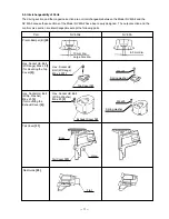
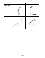
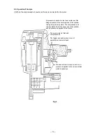
Page 15: ... 12 Pushing Lever 54 Part NV 83A2 NV 83A Bent Welded Cover 105 ...

Page 16: ...enter portion of the cylinder forcing the cylinder upward The compressed air is thereby blocked from the upper end of the cylinder and no pressure is applied to the Piston The accumulator is filled with compressed air The trigger and pushing lever are not operated and remain closed The exhaust vents are open and no air pressure is applied to the valve and feed piston air passage ...

Page 17: ...nward the air below the piston is forced into the return air chamber When the piston passes the middle vent some of the air pressure passes into the return air chamber This supplies auxiliary air to ensure complete return of the piston Cylinder ring 2 When the trigger and pushing lever are operated The trigger and pushing lever are operated simultaneously Note If either the trigger or pushing leve...

Page 18: ...the Piston contacts the Piston Bumper and prevents air leakage If the upper surface of the damper is damaged some air will leak As there is no O ring installed here a very small amount of air will leak from the slight clearance between the components If the operator s grip is loosened air will leak 3 If the trigger and pushing lever are kept pressed ...

Page 19: ... the piston is reduced the air pressure within the return air chamber pushes the piston upward Note If the clearance were any larger the piston would not return if it were smaller driving force would be decreased When the trigger is released the trigger valve closes and the compressed air does not flow into the air passage The air pressure within the valve air passage is discharged through valve e...

Page 20: ...ressure is too low Air passage is clogged with broken pieces of piston bumper etc Feeder piston chamber contains foreign matter such as broken pieces of piston bumper etc Check that the magazine is correctly loaded with specified nails Remove the feed piston and check the feed piston sliding surface of the nose Use specified nails Remove the abnormal nails and load the nailer with proper nails Che...

Page 21: ...distance between the lower end of the nose and the lower end of the pushing lever is 6 5 0 5 mm 0 256 0 020 under the following conditions Pull up safety plunger B until it contacts plunger A Pull up the pushing lever until safety plunger B contacts the safety bolts Check that the nail guide is not abnormal worn deformed damaged etc Check the operation of main nail stopper and sub nail stopper Rep...

Page 22: ...gs Replace the abnormal part Apply grease See item 1 Workpiece is too hard Nailer cannot be used because the material is beyond its applicable range Check if a nail is bent even when driven into soft wood Check that the driver blade tip is not abnormally worn See item 1 Driver blade is worn Replace the part 2 Nails are driven but bent Nails are not completely fed into the injection port Unspecifie...

Page 23: ...end of the pushing lever is 6 5 0 5 mm 0 256 0 020 under the following conditions Pull up plunger B until it contacts plunger A Pull up the pushing lever until plunger B contacts the safety bolt Replace the abnormal part Piston O ring is abnormal worn or damaged Cylinder inside surface is abnormal worn or rough Cylinder O ring is abnormal worn or damaged Sliding surface of the circmference of the ...

Page 24: ...the nail shaft and feeds it Replace the abnormal part Body Nail guide section Nail guide section is abnormal See item 1 Nail guide section Perform idle or actual driving to check if the driver blade is returned completely See item 1 Nail guide section See item 1 Output section piston driver blade etc 4 Nails jam Nails Unspecified nails are used Abnormal nails are mixed Nail heads are too large or ...

Page 25: ... 22 9 2 Possible Causes and Corrections of Air Leakage Air leakage repair location A B C D G H I A A A E F A ...

Page 26: ...Bushing 67 damaged deformed or worn Defective Valve Packing 64 damaged deformed or broken Soiled or damaged valve packing sheet surface of Body B 27 Incursion of foreign materials Defective Gaskets C F 8 6 damaged or yielded Deformed or broken Gasket G 23 Defective O ring S 90 13 or Cylinder O ring 14 of the Cylinder Plate 15 worn deformed or broken Defective Cylinder O ring 16 worn deformed or br...

Page 27: ... 70 worn deformed or cut Defective Feed Piston 70 sliding portion damaged deformed or broken Feed piston Air leak part Cause When trigger valve safety valve are OFF When trigger valve safety valve are ON Slight amount of air is always leaked out of the Feed Piston Cover 75 structurally When trigger valve ON safety valve OFF H Between feed piston cover and nose I ...

Page 28: ...o the O rings and O rings sliding portions When installing the O rings be careful not to damage the O rings and prevent dirt entry Oil required Hitachi pneumatic tool lubricant 1 oz 30 cc oil feeder Code No 877153 4 oz 120 cc oil feeder Code No 874042 1 quart 1 ltr can Code No 876212 If Gasket B 5 is damaged replace it and check that no air is leaking Be especially careful to prevent the entry of ...

Page 29: ...7 and other parts which make up the output section can be removed as illustrated in Fig 10 If it is difficult to remove the Cylinder 17 remove the Tail Cover 31 by referring para 10 5 procedures and push out the Cylinder 17 from the lower part of the main body b Reassembly Reassembly can be accomplished by following the disassembly procedures in reverse However special attention should be given to...

Page 30: ...lts W Flange M6 x 45 1 and as illustrated in Fig 11 remove the Head Cap and Gasket Set 10 Exhaust Valve 9 Exhaust Piece 7 Gasket C 8 and Gasket F 6 b Reassembly Reassembly can be accomplished by following the disassembly procedures in reverse However special attention should be given to the following items Gasket C 8 and Gasket F 6 should be replaced with new genuine Hitachi parts Apply the design...

Page 31: ...ee Fig 12 Remove the Magazine 81 as described in section 10 4 Remove the Pushing Lever 54 as described in section 10 5 With the roll pin puller 3 mm 0 118 dia take out the Roll Pin D3 x 30 63 and remove the Trigger 62 Trigger Plunger 68 and Safety Plunger B 61 Insert the minus hd screwdriver into the groove of the Trigger Valve Bushing 67 and loosen it by turning it to the left being careful not t...

Page 32: ...dia Hex bar wrench 4 mm Wrench M5 1 Disassembly and reassembly of the magazine section a Disassembly See Fig 15 Loosen the Hex Socket Hd Bolt M5 x 20 100 and the Nylon Nut M5 78 then remove the Sleeve 79 Deform Guard 80 using a flat blade screwdriver and disengage it from the Tail Cover 31 Loosen the Machine Screw M5 x 25 44 of the Body B 27 Then the Magazine Ass y 108 can be removed Fig 14 ...

Page 33: ...h Guard 80 positioning the Cover 105 outside Guard 80 Pin 82 Feeder Shaft Ring 83 Hex Socket Hd Bolt M5 x 20 100 Nylon Nut M5 78 Magazine 81 Nylon Nut M5 78 Sleeve 79 Body B 27 Guard 80 Holder Shaft 89 Ratchet Spring 86 Nail Holder 87 Roll Pin D2 5 x 18 88 Spring 90 Pin 82 Magazine Cover 84 Holder Cap 85 Cover 105 Fit hole of the Cover 105 between the convex portion of Magazine 81 and the concave ...

Page 34: ...ts When mounting the Holder Shaft 89 to Magazine 81 check that the Spring 90 is inserted between the concave portion of Magazine 81 and the convex portion of Holder Shaft 89 and then insert the Pin 82 See Fig 16 Check that the Feeder Shaft Rings 83 2 pcs are securely inserted into the grooves of the Pins 82 2 pcs Be careful not to lose the Feeder Shaft Ring 83 Check the following after reassembly ...

Page 35: ... Plunger B 61 Seal Lock Hex Socket Hd Bolt M5 x 10 76 O ring P 22 71 Feed Piston Cover 75 Feed Piston Cover A 74 Feed Spring 72 Bumper 73 Ratchet Spring A 40 Nylock Hex Socket Hd Bolt M8 x 22 37 Adjuster Bolt 38 Roll Pin D2 5 x 18 41 Roll Pin D2 5 x 18 41 Spring 50 Ratchet Spring A 40 Feeder Set 35 Feeder Shaft 36 Feed Piston 70 O ring P 9 69 Pushing Lever 54 Safety Bolt 51 Roll Pin D3 x 45 53 Val...

Page 36: ... Tail Cover 31 b Reassembly Disassembly procedures should be followed in the reverse order Note the following points Safety Plunger B 61 is apt to come off during disassembly Be sure to check that Safety Plunger B 61 is securely mounted during reassembly Insert the protrusion of the Valve Guard 52 between the Roll Pin D3 x 30 63 and Body B 27 See Fig 18 Insert the Roll Pin D3 x 45 53 in the hole o...

Page 37: ...and Feed Piston 70 Confirm that the hook portions two places of the Feeder Spring 33 are properly fitted into the grooves provided in the Feeder Set 35 Prior to reassembly apply grease Hitachi Motor Grease No 29 Code No 930035 is recommended to O ring P 9 69 O ring P 22 71 O ring sliding portions of the Feed Piston 70 and Tail Cover 31 However be careful not to apply excessive amount of greases Ex...

Page 38: ... 93 Main Stopper Spring 103 and Cover 105 can be removed Remove the Roll Pin D3 x 28 102 from the Nail Guide 95 with the roll pin puller Then Sub Nail Stopper 92 and Feeder Set 35 can be removed Fig 19 Disassembly and reassembly of nail guide sub nail stopper and other parts Sub Stopper Spring 93 Sub Nail Stopper 92 Lock Shaft 94 Roll Pin D3 x 28 102 Main Stoppr Spring 103 Cover 105 Feeder Set 35 ...

Page 39: ...81 See Fig 15 10 6 Grip Rubber The Model NV 83A2 is equipped with the grip rubber handle that is common to the Model NR 83AA2 However the grip rubber is not supplied as a spare part because it is difficult to detach attach the grip rubber If replacement of the grip rubber is required replace the Body B 27 or attach the grip tape How to attach the grip tape and the fixing tape Grip tape A Code No 8...

Page 40: ... position Recheck the tightening torque of each screw Check that Pushing Lever 54 slides smoothly Check that the machine will not operate only by pulling the Trigger 62 Also check that the machine will not operate only by depressing the Pushing Lever 54 Push Sub Nail Stopper 92 and Feeder Set 35 with fingers to check that they smoothly return to position Check that the Feed Piston 70 operates prop...

Page 41: ...ariable NV 83A2 Work Flow Exhaust Cover Exhaust Piece Exhaust Valve Head Cap Gasket Set Gasket x 3 60 min 50 Cylinder Plate Cylinder Cylinder Ring Cylinder Spring Cylinder Guide Piston Bumper A Cylinder O ring x 4 O ring x 3 General Assembly Feeder Set Feeder Spring Nail Guide Sub Nail Stopper Guide Lock Spring x 4 Tail Cover Magazine Ass y Body Feed Piston O ring x 2 Feed Spring Bumper Feed Pisto...

Page 42: ...0 21 13 22 13 23 24 25 26 27 28 29 30 31 32 33 34 35 36 37 38 39 40 41 42 43 44 45 46 47 48 49 50 51 52 53 54 55 56 57 58 59 60 61 62 63 64 65 59 66 67 58 68 69 70 71 72 73 74 75 76 77 78 79 80 78 81 82 83 82 84 83 85 86 87 88 89 90 81 90 91 92 93 94 95 96 97 98 99 100 101 102 103 104 105 106 107 108 501 502 503 504 505 506 507 ...

Page 43: ...R SPRING 1 21 877 322 BASE WASHER 1 22 877 310 CYLINDER GUIDE 1 23 877 327 GASKET G 1 24 883 513 WARNING LABEL A 1 FOR FRA 25 878 184 WARNING LABEL 1 26 878 183 WARNING LABEL 1 FOR FRA 27 884 040 BODY B 1 28 877 315 CYLINDER O RING I D 63 9 1 29 883 511 PISTON BUMPER B 1 30 877 334 GASKET A 1 31 884 020 TAIL COVER 1 32 877 826 FEEDER SHAFT RING 1 33 877 851 FEEDER SPRING 1 34 949 496 ROLL PIN D3X1...

Page 44: ...76 796 O RING P 22 1 72 877 144 FEED SPRING 1 73 877 711 BUMPER 1 74 877 827 FEED PISTON COVER A 1 75 877 713 FEED PISTON COVER 1 76 877 839 SEAL LOCK HEX SOCKET HD BOLT M5X10 2 77 878 305 MAGAZINE BUSHING 1 78 877 371 NYLON NUT M5 2 79 882 907 SLEEVE 1 80 884 028 GUARD 1 81 884 033 MAGAZINE 1 82 883 111 PIN 2 83 877 826 FEEDER SHAFT RING 2 84 884 034 MAGAZINE COVER 1 85 884 038 HOLDER CAP 1 86 88...

Page 45: ...1 103 876 681 MAIN STOPPER SPRING 1 104 877 469 NAIL GUIDE COVER 1 105 884 023 COVER 1 106 884 022 PLATE 1 107 877 838 SEAL LOCK HEX SOCKET HD BOLT M4X 8 2 108 884 032 MAGAZINE ASS Y 1 INCLUD 81 90 501 872 422 HEX BAR WRENCH 6MM 1 502 944 459 HEX BAR WRENCH 5MM 1 503 944 458 HEX BAR WRENCH 4MM 1 504 875 769 EYE PROTECTOR 1 505 882 413 CAUTION TAG 1 506 882 414 LEAFLET 1 FOR USA 507 877 153 PNEUMAT...

Page 46: ......

Reviews: