English
14
3. Adjustment of cutter blade height:
CAUTION:
●
As the set gauge has been accurately factory
adjusted, never attempt to loosen it.
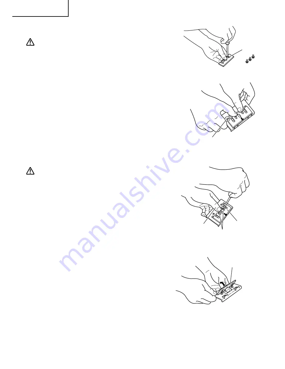
(1) After attaching the back metal to the cutter
blade, temporarily fasten them together with
machine screws, as shown in Fig.13.
(2) Insert the set gauge plate spring into the hole on
the back metal and heavily push the plate spring
in the direction indicated by the arrow in Fig.14
until it snaps into the correct position.
(3) Holding the set gauge with the blade edge
facing downward as shown in Fig.15, loosen
the temporarily fastened machine screws and
lightly push the cutter blade with a thumb until
the cutter blade gently touches plate.
CAUTION:
●
Do not push the blade with excessive pressure.
Excessive pressure could cause maladjustment of
the blade height.
(4) Finally, retighten the machine screws to securely
fasten the cutter blade and the back metal,
thereby completing the blade height adjustment
procedure.
(5) Holding the set gauge as shown in Fig.16, push
upward on the back metal and remove it from
the set gauge.
(6) The cutter blade is now ready to be mounted on
the planer as described in the section on cutter
blade assembly.
Fig. 13
Fig. 14
Machine
screw
Fig. 15
Align the back metal end with
on extruded portion.
Lightly push with
a thumb.
Plate
Machine screw
Fig. 16
Push up the back
metal for beneath


