Chapter 2
Installation environment
•
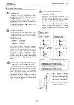
Avoid installing the inverter in a place where the
inverter is subject to dust, corrosive gases,
explosive
mist, or salt water.
•
Foreign
failure.
dusty environment, install the inverter inside a
totally enclosed panel.
Installation method and position
•
Install the inverter vertically and securely with
screws or bolts on a surface that is free from
vibrations and that can bear the inverter weight.
•
If the inverter is not installed properly, its cooling
performance may be degraded and tripping or
inverter damage may result.
Mounting in an enclosure
•
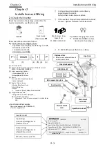
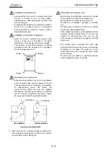
When mounting multiple inverters in an enclosure
with a ventilation fan, carefully design the layout
of the ventilation fan, air intake port, and inverters.
An
inappropriate
layout
will
reduce
t
inverter
temperature.
inverter ambient temperature will remain within
the range specified in the specification table.
When the
the incoming dust may
a position to avoid this falling dust
(Acceptable)
Inverter
Screw
Screw
Chapter 2
Installation environment
Avoid installing the inverter in a place where the
inverter is subject to dust, corrosive gases,
explosive gases, flammable gases, grinding fluid
mist, or salt water.
Foreign particles entering the i
. If you use the inverter in a considerably
dusty environment, install the inverter inside a
totally enclosed panel.
Installation method and position
Install the inverter vertically and securely with
screws or bolts on a surface that is free from
vibrations and that can bear the inverter weight.
If the inverter is not installed properly, its cooling
performance may be degraded and tripping or
inverter damage may result.
Mounting in an enclosure
When mounting multiple inverters in an enclosure
with a ventilation fan, carefully design the layout
of the ventilation fan, air intake port, and inverters.
An
inappropriate
layout
will
reduce
t
inverter-cooling effect and
temperature. Plan the layout
inverter ambient temperature will remain within
the range specified in the specification table.
the inverter is installed
the incoming dust may adhere to
a position to avoid this falling dust
(Acceptable)
Ventilation
Position of ventilation fan
Screw
crew
Installation environment
Avoid installing the inverter in a place where the
inverter is subject to dust, corrosive gases,
gases, flammable gases, grinding fluid
particles entering the inverter will cause
If you use the inverter in a considerably
dusty environment, install the inverter inside a
totally enclosed panel.
Installation method and position
Install the inverter vertically and securely with
screws or bolts on a surface that is free from
vibrations and that can bear the inverter weight.
If the inverter is not installed properly, its cooling
performance may be degraded and tripping or
inverter damage may result.
Mounting in an enclosure
When mounting multiple inverters in an enclosure
with a ventilation fan, carefully design the layout
of the ventilation fan, air intake port, and inverters.
An
inappropriate
layout
will
reduce
t
cooling effect and raise the ambient
Plan the layout properly
inverter ambient temperature will remain within
the range specified in the specification table.
inverter is installed below ventilatio
adhere to the inverter.
a position to avoid this falling dust.
(Unacceptable)
Inverter
Ventilation
Position of ventilation fan
Screw
Screw
Avoid installing the inverter in a place where the
inverter is subject to dust, corrosive gases,
gases, flammable gases, grinding fluid
nverter will cause
If you use the inverter in a considerably
dusty environment, install the inverter inside a
Installation method and position
Install the inverter vertically and securely with
screws or bolts on a surface that is free from
vibrations and that can bear the inverter weight.
If the inverter is not installed properly, its cooling
performance may be degraded and tripping or
When mounting multiple inverters in an enclosure
with a ventilation fan, carefully design the layout
of the ventilation fan, air intake port, and inverters.
An
inappropriate
layout
will
reduce
t
raise the ambient
properly so that the
inverter ambient temperature will remain within
the range specified in the specification table.
below ventilation fan,
the inverter. Place in
(Unacceptable)
Ventilation
Inverter
Position of ventilation fan
Screw
Screw
2-3
Avoid installing the inverter in a place where the
inverter is subject to dust, corrosive gases,
gases, flammable gases, grinding fluid
nverter will cause of
If you use the inverter in a considerably
dusty environment, install the inverter inside a
Install the inverter vertically and securely with
screws or bolts on a surface that is free from
vibrations and that can bear the inverter weight.
If the inverter is not installed properly, its cooling
performance may be degraded and tripping or
When mounting multiple inverters in an enclosure
with a ventilation fan, carefully design the layout
of the ventilation fan, air intake port, and inverters.
An
inappropriate
layout
will
reduce
the
raise the ambient
so that the
inverter ambient temperature will remain within
n fan,
lace in
Ventilation
Reduction of enclosure size
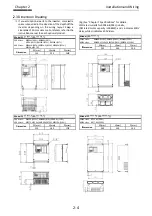
•
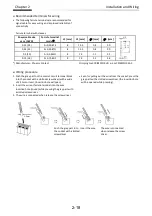
External heat sink installation may reduce internal
heat emission
•
External heat sink mounting for the inverter
P1-00044-
and
P1-00041-
requires an optional
•
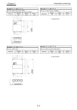
Other models than above can be installed with the
originally attached metal
inverter
enclosure panel according to the specified cutting
dimensions.
•
The cooling s
positioned outside the enclosure has a cooling fan.
Therefore, do not place the enclosure in any
environment where it is exposed to water
oil mist, or dust.
•
The heat sink part reaches a high temperature.
Install a pr
Installation and Wiring
Reduction of enclosure size
External heat sink installation may reduce internal
heat emission and reduce the enclosure si
External heat sink mounting for the inverter
-L to P1-00228
-H to P1-00126
requires an optional metal
Other models than above can be installed with the
originally attached metal
for external heat sink, cut out the
enclosure panel according to the specified cutting
dimensions.
The cooling section (including the heat sink)
positioned outside the enclosure has a cooling fan.
Therefore, do not place the enclosure in any
environment where it is exposed to water
oil mist, or dust.
he heat sink part reaches a high temperature.
Install a protection cover as needed.
Installation and Wiring
Reduction of enclosure size
External heat sink installation may reduce internal
and reduce the enclosure si
External heat sink mounting for the inverter
00228-L (P1-004L to P1
00126-H (P1-007H to P1
metal fitting.
Other models than above can be installed with the
originally attached metal fitting. To mount the
for external heat sink, cut out the
enclosure panel according to the specified cutting
ection (including the heat sink)
positioned outside the enclosure has a cooling fan.
Therefore, do not place the enclosure in any
environment where it is exposed to water
he heat sink part reaches a high temperature.
otection cover as needed.
Installation and Wiring
External heat sink installation may reduce internal
and reduce the enclosure size.
External heat sink mounting for the inverter
004L to P1-037L)
007H to P1-037H)
Other models than above can be installed with the
. To mount the
for external heat sink, cut out the
enclosure panel according to the specified cutting
ection (including the heat sink)
positioned outside the enclosure has a cooling fan.
Therefore, do not place the enclosure in any
environment where it is exposed to water drops,
he heat sink part reaches a high temperature.
otection cover as needed.
Installation and Wiring
External heat sink installation may reduce internal
037L)
037H)
Other models than above can be installed with the
. To mount the
for external heat sink, cut out the
enclosure panel according to the specified cutting
ection (including the heat sink)
positioned outside the enclosure has a cooling fan.
Therefore, do not place the enclosure in any
drops,
he heat sink part reaches a high temperature.
Summary of Contents for P1-00041HFEF
Page 6: ...0 5 Contents Contents Memo ...
Page 42: ...2 26 Chapter 2 Installation and Wiring Memo ...
Page 129: ...Index Index 3 memo ...
Page 130: ...Index Index 4 memo ...

