4-3
Chapter 4
Safety Function
■
Name plate
The P1-FS name plate gives the following information.
■
Status indicator lamp
The status indicator lamp on the front side indicates the
statuses of P1-FS. The statuses and the conditions are
explained below.
Lamp
status
Condition
OFF
P1-FS initial diagnosis error or power-off
ON
Normally activated P1-FS after the initial
diagnosis was completed
Blinking
The P1-FS password still on its factory
setting or during the SFS function
■
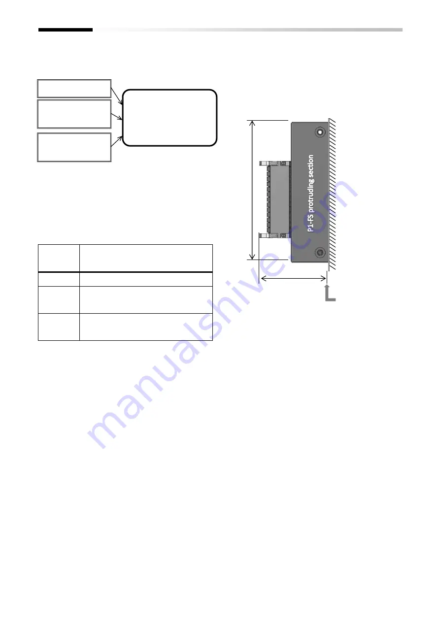
Dimensions after installation
The dimensions of the P1-FS after it is installed on the
inverter are shown in the image below.
As shown on the image, a part of the P1-FS will stand out
from the SJ-P1. Please pay attention when installing the
device.
SJ
-P1
in
ve
rt
er
SJ-P1 front
surface
View from the right side of the SJ-P1
47mm
9
6
.5
m
m
Device model
P1-FS
○○○○
*******△□□□□
Factory control
number
Manufacture number
(MFG No
)
Summary of Contents for P1
Page 2: ...The picture is an example of installing P1 FS to SJ P1 ...
Page 8: ...C 3 Index Memo ...
Page 10: ...1 2 Chapter 1 Safety Precaution Risk Memo ...
Page 12: ...2 2 Chapter 2 Introduction to the Safety Function Guide Memo ...
Page 62: ...7 2 Chapter 7 Commissioning Memo ...
Page 64: ...8 2 Chapter 8 Verification and Validation Memo ...
Page 68: ...10 2 Chapter 10 Maintenance Memo ...
Page 72: ...11 4 Chapter 11 Specification and Technical data Memo ...


