


4-4
Chapter 4
Safety Function
4.4.2
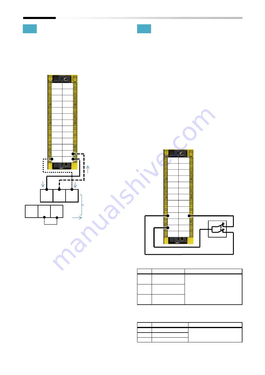
How to connect STO signals
Please refer to the wiring examples below for wirings on
terminals.
■
Wiring
e.g. Internal power Source logic
*) Please connect between STC and CMS.
4.4.3
Input terminal
Input signals of Safety function are redundant inputs of
terminal group -1 and terminal group -2.
When voltage is applied to each input, currents flow on
each safety path inactivating the Safety function.
When voltage is removed from at least one of the
redundant inputs, the Safety function is activated by the
corresponding safety path.
The voltage source for input signals of safety function is
selectable from the 24V power supply for input terminals
(P24E) or an externally prepared DC24V power supply.
The external power supply must be SELV or PELV DC24V
power supply.
An example of wiring the switch to input S1-1 and S1-2 is
shown below.
■
In case of use of the 24V power supply for input
terminals (P24E)
■
Selecting input terminal function
It can be set the input terminal function.
No.
Name
Related data
0-11
Safety Function
Select Input 1
00:Invalid/01:STO-A/02:SS1-A/
03:SBC-A/04:SLS-A/05:SDI-A/
11:STO-B/12:SS1-B/13:SBC-B/
14:SLS-B/15:SDI-B
0-12
Safety Function
Select Input 2
0-13
Safety Function
Select Input 3
■
NO/NC switching function
NO/NC state can be switched only path 2.
No.
Name
Related data
0-31
Input arrangement 1
00:NC(path 1 and path 2) /
01:NC(path 1) and NO(path2)
0-32
Input arrangement 2
0-33
Input arrangement 3
S12
S12
S11
S11
24V1 24V2
CMo1 CMo2
S13
S13
24V3 24V4
CMo3 CMo4
S3
S3
S2
S2
S1
S1
RLS
CME
P24E
STC
ST1
ST2
P24S
STC
CMS
ST1
ST2
STC
: Current flow
Short wire
Terminal block of SJ-P1
S12
S12
S11
S11
24V1 24V2
CMo1 CMo2
S13
S13
24V3 24V4
CMo3 CMo4
S3
S3
S2
S2
S1
S1
RLS
CME
P24E
STC
ST1
ST2
Summary of Contents for P1
Page 2: ...The picture is an example of installing P1 FS to SJ P1 ...
Page 8: ...C 3 Index Memo ...
Page 10: ...1 2 Chapter 1 Safety Precaution Risk Memo ...
Page 12: ...2 2 Chapter 2 Introduction to the Safety Function Guide Memo ...
Page 62: ...7 2 Chapter 7 Commissioning Memo ...
Page 64: ...8 2 Chapter 8 Verification and Validation Memo ...
Page 68: ...10 2 Chapter 10 Maintenance Memo ...
Page 72: ...11 4 Chapter 11 Specification and Technical data Memo ...


