


4-5
Chapter 4
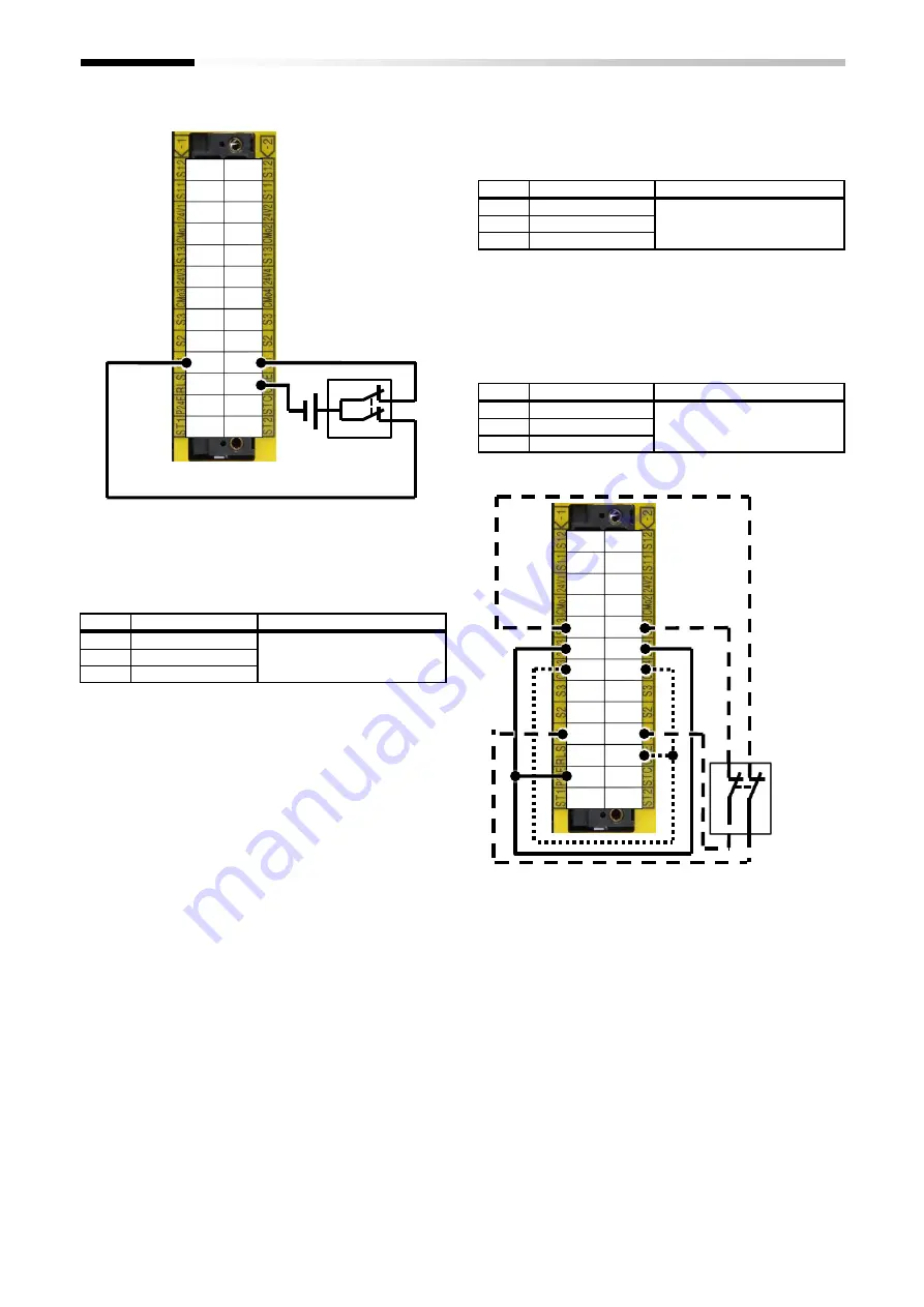
Safety Function
■
In case of use of the external power supply
■
Setting input sensitivity
Signal level is completed after the input sensitivity time is
passed from switching the signal level.
No.
Name
Related data
0-61
Input 1 sensitivity
0.001 to 1.000s
0-62
Input 2 sensitivity
0-63
Input 3 sensitivity
*) In case that
malfunction occurs due to noise, please set
the above parameters for a long time.
■
Setting allowed gap time
Allowed gap time is set for switching redundant input
simultaneously. Mainly, the time difference between
redundant inputs can be allowed when the redundant
inputs are released.
No.
Name
Related data
0-81
Input 1 gap time
0.001 to 1.000s
0-82
Input 2 gap time
0-83
Input 3 gap time
*)
If the allowed gap time is short, the Safety function
cannot be released
.
■
Checking test pulse input
P1-FS can check the input terminals for test pulse from
output terminal S13. The path error will occur if the test
pulse is not recognized correctly.
No.
Name
Related data
0-51
Test pulse check 1
00:Inactivated / 01:Activated
0-52
Test pulse check 2
0-53
Test pulse check 3
S12
S12
S11
S11
24V1 24V2
CMo1 CMo2
S13
S13
24V3 24V4
CMo3 CMo4
S3
S3
S2
S2
S1
S1
RLS
CME
P24E
STC
ST1
ST2
S12
S12
S11
S11
24V1 24V2
CMo1 CMo2
S13
S13
24V3 24V4
CMo3 CMo4
S3
S3
S2
S2
S1
S1
RLS
CME
P24E
STC
ST1
ST2
24V
Summary of Contents for P1
Page 2: ...The picture is an example of installing P1 FS to SJ P1 ...
Page 8: ...C 3 Index Memo ...
Page 10: ...1 2 Chapter 1 Safety Precaution Risk Memo ...
Page 12: ...2 2 Chapter 2 Introduction to the Safety Function Guide Memo ...
Page 62: ...7 2 Chapter 7 Commissioning Memo ...
Page 64: ...8 2 Chapter 8 Verification and Validation Memo ...
Page 68: ...10 2 Chapter 10 Maintenance Memo ...
Page 72: ...11 4 Chapter 11 Specification and Technical data Memo ...


