4-7
Chapter 4
Safety Function
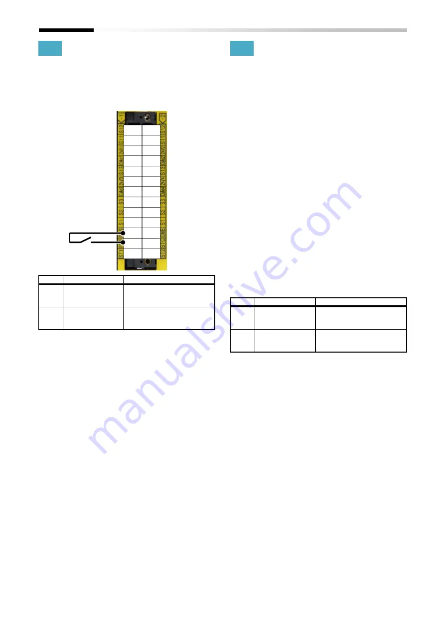
4.4.5
Release terminal
The function release is activated when voltage is removed
from release terminal after voltage is applied to release
terminal and currents flow. Releasing by release signal is
activated when the parameter [1-12]/[2-12] sets to
02:With release signal.
■
Related parameter
No.
Name
Related data
1-12
STO-A release mode
00:Without release signal /
01:With safety signal /
02:With release signal
2-12
STO-B release mode
00:Without release signal /
01:With safety signal /
02:With release signal
4.4.6
Holding function of STO state
When the parameter [1-12]/[2-12] is set by 01:With safety
signal or 02:With release signal, STO state can be held until
releasing intentionally by safety signals or release signal
after STO state is activated.
When the parameter [1-12]/[2-12] is set by 00:Without
release signal, STO state can be released automatically
after safety inputs are released. In this case, inverter starts
to output the power to the motor automatically after
safety inputs are released when the run command is input
after releasing STO inputs or the run command is kept
before releasing STO input. Considering the above-
mentioned behavior, please apply at least one of the
measures below in order to fulfill the requirement of
EN60204-1:
(1)
The RUN command is released simultaneously when
the STO inputs are activated and then given when
restart of the inverter is requested intentionally by an
operator of the system.
(2)
The system is designed so that the safety inputs to P1-
FS are released only when restart of the system is
requested intentionally by an operator of the system.
■
Related parameter
No.
Name
Related data
1-12
STO-A release mode
00:Without release signal /
01:With safety signal /
02:With release signal
2-12
STO-B release mode
00:Without release signal /
01:With safety signal /
02:With release signal
S12
S12
S11
S11
24V1 24V2
CMo1 CMo2
S13
S13
24V3 24V4
CMo3 CMo4
S3
S3
S2
S2
S1
S1
RLS
CME
P24E
STC
ST1
ST2
Summary of Contents for P1
Page 2: ...The picture is an example of installing P1 FS to SJ P1 ...
Page 8: ...C 3 Index Memo ...
Page 10: ...1 2 Chapter 1 Safety Precaution Risk Memo ...
Page 12: ...2 2 Chapter 2 Introduction to the Safety Function Guide Memo ...
Page 62: ...7 2 Chapter 7 Commissioning Memo ...
Page 64: ...8 2 Chapter 8 Verification and Validation Memo ...
Page 68: ...10 2 Chapter 10 Maintenance Memo ...
Page 72: ...11 4 Chapter 11 Specification and Technical data Memo ...


