S-2
Introduction
S.3 Relevant document
S.4 List of abbreviation and
technical terms
A
Term/Abbreviation
Description
AWG
American wire gauge
Standardized wire gauge used in
North America
B
Term/Abbreviation
Description
Basic Guide
The
documentation
that
provides basic information to
handle the inverter
C
Term/Abbreviation
Description
CAT.
Category
Structural Classification of the
safety-related parts defined in
EN ISO13849-1 (B,1,2,3,4)
CCF
Common Cause Failure (EN ISO
13849-1)
Failure, which is the result of
one or more events, causing
concurrent failure of two or
more separate channels in a
multiple
channel
system,
leading to failure of the Safety
function
CE marking
A
mandatory
conformity
marking for products sold
within the European Economic
Area.
Charge lamp
The lamp indicates power
supply status of the main circuit
of the inverter. Even after
powered down, the internal
voltage remains while the lamp
lights.
Control power
supply
Internal
power
supply
necessary for powering up the
logic board and configuring the
inverter using operator keypad.
Supplying power to R0T0
terminal or P+, P- terminal can
power up the internal power
supply.
*) Trademark
Some proper nouns such as product name or function
names may be registered as trademark or registered
trademark. Particularly this documentation does not
describes ® mark or
TM
mark.
C
Term/Abbreviation Description
Common cause
failure
In a redundant system,
multiple channels can be
simultaneously faulted by
certain factors.
D
Term/Abbreviation
Description
Dangerous failure
Failure of a component and/or
subsystem and/or system that
plays a part in implementing
the Safety function
DC
Diagnostic coverage (%) (EN
ISO 13849-1)
E
Term/Abbreviation
Description
EMC
Electromagnetic compatibility
F
Term/Abbreviation Description
Functional Safety
Reduce the risk of harm to an
acceptable level via design
changes or by applying
appropriate safety measures
H
Term/Abbreviation
Description
HFT
Hardware
fault
tolerance
(IEC61508)
I
Term/Abbreviation
Description
I/O
Input / Output
IGBT
Insulated
gate
bipolar
transistor
Inverter model code
The model code written on the
specification label of the
inverter.
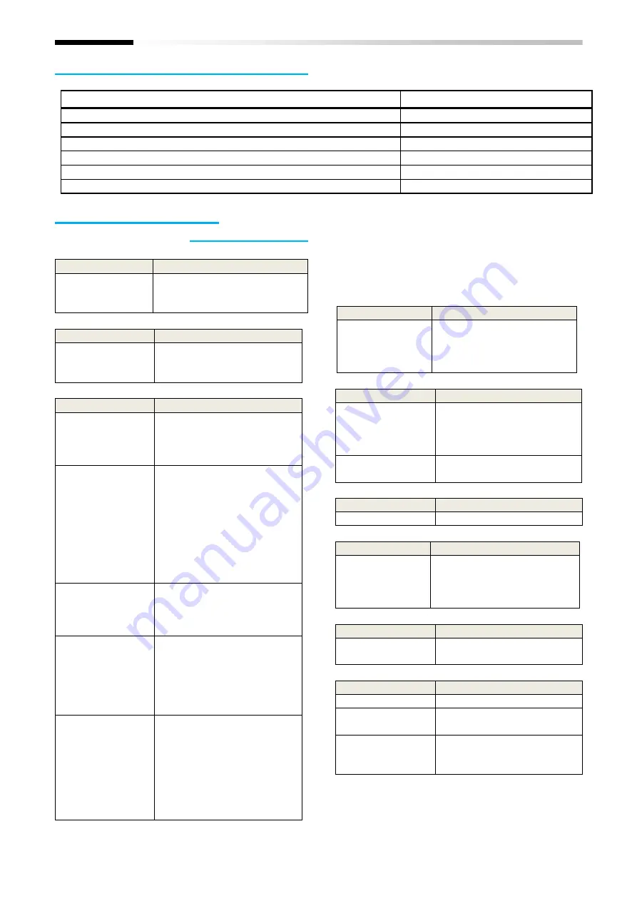
Document name
Document code
SJ Series P1 User’s Guide
NT251X
SJ Series P1 Basic Guide
NT2511X
SJ Series P1 Safety Function Guide
NT2512X
SJ Series P1 Safety Function Guide Supplement
NTZ2512X
P1-FS Safety Function Guide (this documentation)
NT2582X
P1-FS Safety Function Guide Supplement
NTZ2582X
Summary of Contents for P1
Page 2: ...The picture is an example of installing P1 FS to SJ P1 ...
Page 8: ...C 3 Index Memo ...
Page 10: ...1 2 Chapter 1 Safety Precaution Risk Memo ...
Page 12: ...2 2 Chapter 2 Introduction to the Safety Function Guide Memo ...
Page 62: ...7 2 Chapter 7 Commissioning Memo ...
Page 64: ...8 2 Chapter 8 Verification and Validation Memo ...
Page 68: ...10 2 Chapter 10 Maintenance Memo ...
Page 72: ...11 4 Chapter 11 Specification and Technical data Memo ...


