


4-29
Chapter 4
Safety Function
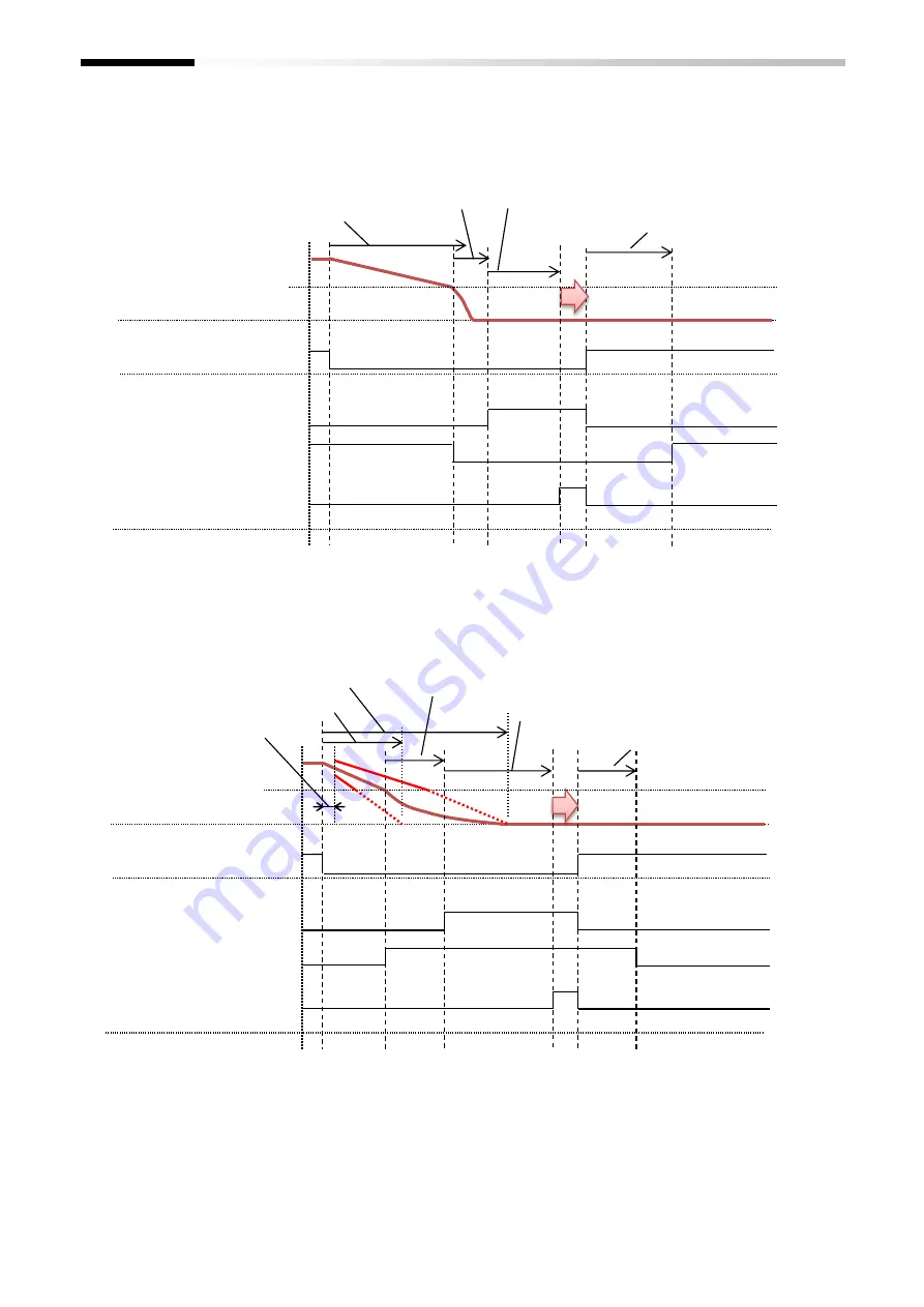
e.g. Case: SS1-B then SBC-B before STO-B
[2-31]SBC-B Time linkage=03(SS1 then SBC before STO),
[2-22]SS1-B monitoring method=00(Time),
[2-12]STO-B release mode=01(With safety signal) and
[2-36]SBC-B release level =0.00%:
e.g. Case: SS1-B then SBC-B after STO-B
[2-31]SBC-B Time linkage=02( SS1 then SBC after STO),
[2-22]SS1-B monitoring method=01(frequency),
[2-12]STO-B release mode=01(With safety signal) and
[2-36]SBC-B release level =0.00%:
SBC-B
Input
Output
STO-B monitoring
Motor speed
SBC-B control
Open
Short
STO-B completed
Active
Inactive
Active
Inactive
Inactive
Active
Releasable
[2-11]STO-B Keep time
[2-33]Wait time SBC-B before STO-B
[2-35]SBC-B STO-B Release wait time
[2-34]SBC-B frequency
[2-23]SS1-B Active time
SBC-B
Input
Output
STO-B monitoring
Motor speed
SBC-B control
Open
Short
[2-34]SBC-B frequency
STO-B completed
Active
Inactive
Active
Inactive
Inactive
Active
Releasable
[2-26]SS1-B Wait time
[2-24]SS1-B Min Deceleration time
[2-25]SS1-B Max Deceleration time
[2-33]Wait time SBC-B before STO-B
[2-11]STO-B Keep time
[2-35]SBC-B STO-B Release wait time
Summary of Contents for P1
Page 2: ...The picture is an example of installing P1 FS to SJ P1 ...
Page 8: ...C 3 Index Memo ...
Page 10: ...1 2 Chapter 1 Safety Precaution Risk Memo ...
Page 12: ...2 2 Chapter 2 Introduction to the Safety Function Guide Memo ...
Page 62: ...7 2 Chapter 7 Commissioning Memo ...
Page 64: ...8 2 Chapter 8 Verification and Validation Memo ...
Page 68: ...10 2 Chapter 10 Maintenance Memo ...
Page 72: ...11 4 Chapter 11 Specification and Technical data Memo ...


