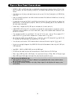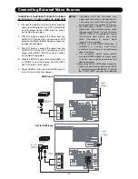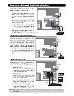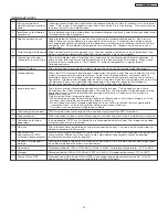
50
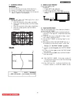
7 SCREEN CHECK
Preparation
(1) Set AC120±1V.
(2) Turn on the power and leave it more than 5 min.
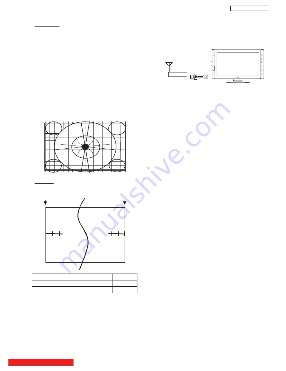
(3) Receive circle pattern at 4:3 Expanded mode.
(4) Input 480p and 1080i circle pattern into Component
video 3
. (ASPECT 16:9 Standard)
Checking
(1) Receive RF, 480p
and
1080i signal,
then check
the
following items 1~4:
1. Check the symmetry of the pattern (right/left).
2. Check the horizontal position and the balance
(right/left).
3. Check the symmetry of the pattern (top/bottom).
4. Check the vertical position and the balance
(top/bottom).
Remarks
3
SCREEN
0 1 2
2 1 0
A
B
8 HDMI ADJUSTMENT
(1) DVI compatibility check
Preparation
1. Prepare HDTV signal generator.
2. Select
DVI mode then
1080i format
3. Connect HDMI-DVI cable to the
HDM
I input on the
PDP set.
BACK TO ADJUSTMENTS
SIGNAL ASPECT
SPEC(A,B)
Hitachi circle pattern
16:9 Standard
1
0 +/- 0.5
ATSC
DVI - HDMI
conversion cable
Set Top Box
9 FACTORY RESET
After all of the adjustments of main chassis are finished,
perform FACTORY RESET.
(1) Enter Adjustment Mode by the method described in
sub-item 1-1 from page
43
. (“Adjustment Procedure
Start-up”).
(2) From the first menu in Adjustment Mode, select
FACT RESET adjustment code.
(3) Activate FACT RESET by pressing “Right” cursor
key once.
(
4
) The procedure of the FACTORY RESET process is
the following and the DATA table is shown next.
(
7
)
When PDP turns ON , it will tune CH03 this is the
complete operation
of FACTORY RESET process.
Process of
FACTORY RESET operation.
A screen is colored
magenta
when FACTORY RESET
start.
A screen is colored
green
when FACTORY RESET
finish normally.
A screen is colored
RED
when FACTORY RESET
finish abnormally.
(6) After FACTORY RESET, it should be unplug AC
cord.Unplug and plug AC cord and then all settings
and data are updated.
①
②
③
DW
3
U
Summary of Contents for P50H4011
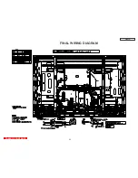
Page 64: ...DW3U 63 FINAL WIRING DIAGRAM TABLE OF CONTENTS ...
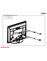
Page 76: ...FINAL ASSEMBLY GUIDE TABLE OF CONTENTS 75 DW3U ...
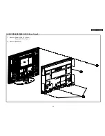
Page 77: ...FINAL ASSEMBLY GUIDE 76 DW3U ...
Page 78: ...FINAL ASSEMBLY GUIDE 77 DW3U ...
Page 79: ...FINAL ASSEMBLY GUIDE 78 DW3U ...
Page 80: ...FINAL ASSEMBLY GUIDE 79 DW3U ...
Page 81: ...FINAL ASSEMBLY GUIDE 80 DW3U ...
Page 82: ...FINAL ASSEMBLY GUIDE 81 DW3U ...
Page 83: ...FINAL ASSEMBLY GUIDE 82 DW3U ...
Page 84: ...FINAL ASSEMBLY GUIDE 83 DW3U ...
Page 97: ...BACK TO TABLE OF CONTENTS 96 PRINTED CIRCUIT BOARDS DW3 U TERMINAL PWB Component side DW3 U ...
Page 98: ...PRINTED CIRCUIT BOARDS DW3 U TERMINAL PWB Solder side DW3 U 97 ...
Page 99: ...PRINTED CIRCUIT BOARDS DW3 U SD PWB Component side DW3 U 98 ...
Page 100: ...PRINTED CIRCUIT BOARDS DW3 U SD PWB Solder side DW3 U 99 ...
Page 102: ...PRINTED CIRCUIT BOARDS DW3 U FILTER PWB Component side DW3 U 101 Component side ...
Page 103: ...PRINTED CIRCUIT BOARDS DW3 U FILTER PWB Solder side DW3 U 102 Solder side ...
Page 123: ......

