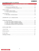
TABLE OF CONTENTS
DW
3
U
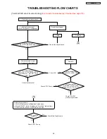
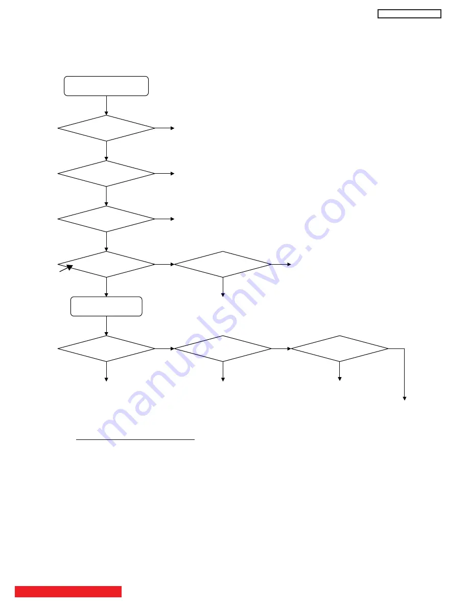
DW3 TROUBLESHOOTING FLOW CHARTS
55
[Power Supply troubleshooting]
㧖
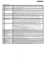
) Power-On control signals for Power Supply Unit (PSU here after)
(1) AC (Master Power) switch : ON
Æ
PSU outputs STBY+5V CN63 pin 1 and STBY +3.3V CN63 pin 3.
(2) PoWER_1 (+3.3V CN63 pin 6) : High
Æ
PSU o5.6V.
(3) PoWER_2 (+3.3V CN63 pin 7) : High
Æ
PSU o10V and +12V.
(4) Vcego (+2.69V CN68 pin 7) : High
Æ
PSU outputs Vcc+5.1V for PDP Panel.
(5) Vsago (+2.69V CN68 pin 8) : High
Æ
PSU outputs Va and Vs for PDP Panel.
If any control signal does not rise, Power Supply can not output the voltage.
PoWER_1 or _2 : does not rise ----- Suspect Main-Digital PWB trouble or connection.
Vcego/Vsago : does not rise ----- PDP Panel Module (Suspect Logic PWB) trouble or connection.
However, Vcego should rise when PNLRST (Connector EC01 pin 43 at Main-Digital board) outputs a High and
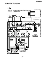
Vsago should rise when PNLoN (Connector EC01 pin 42 at Main-Digital board) also outputs a High. (See page 61 diagram)
Does Power Indicator
blink Red?
Video Power Save Mode
(Input:1
㨪
3, Front Input have no signal)
Yes
No
No Power or
(No picture, and No sound)
No
Fan Alarm
- FAN connector disconnected, FAN trouble
or Regulator circuit (IP03 on Terminal PWB) trouble
Yes
Check Power Supply Unit. (
㧖5GGPQVGUDGNQY
also check Fuse
or AC-Inlet / Connector
Is Power Indicator
lit Orange?
Is Power Indicator
Lit?
Does Power Supply Unit
5V?
Yes
Check Main-Digital board.
No
No
Yes
Power Indicator
blue is lighted normally.
Check Power Supply Unit. (
㧖
Does Power Supply Unit
10V/12V?
No
Yes
Check Power Supply Unit. (
㧖
Does Power Supply Unit
output Va/Vs?
No
Yes
Check Main-Digital board
or Terminal PWB
Does PDP Burn-In mode
operates normally?
Check PDP module.
No
Yes
Does Power Indicator
blink Blue?
No
PDP Module Alarm
- Refer to the page “PDP Panel self-diagnosis function” page 57.
Yes
For
SBY
+5V
, c
heck
C
N63
p
in
1
(Always
p
resent
w
ith
A
C)
Note: Power_1 and Power _2 are high
for the about 2 minutes when AC
is first applied or always high
if "Stand-By Mode" is turned on
in Customer's Menu.
Burn-In mode = menu-menu-menu-9-select
pressed slowly. Repeat to Exit.
After pressing
power On.
Summary of Contents for P50H4011
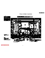
Page 64: ...DW3U 63 FINAL WIRING DIAGRAM TABLE OF CONTENTS ...
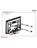
Page 76: ...FINAL ASSEMBLY GUIDE TABLE OF CONTENTS 75 DW3U ...
Page 77: ...FINAL ASSEMBLY GUIDE 76 DW3U ...
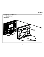
Page 78: ...FINAL ASSEMBLY GUIDE 77 DW3U ...
Page 79: ...FINAL ASSEMBLY GUIDE 78 DW3U ...
Page 80: ...FINAL ASSEMBLY GUIDE 79 DW3U ...
Page 81: ...FINAL ASSEMBLY GUIDE 80 DW3U ...
Page 82: ...FINAL ASSEMBLY GUIDE 81 DW3U ...
Page 83: ...FINAL ASSEMBLY GUIDE 82 DW3U ...
Page 84: ...FINAL ASSEMBLY GUIDE 83 DW3U ...
Page 97: ...BACK TO TABLE OF CONTENTS 96 PRINTED CIRCUIT BOARDS DW3 U TERMINAL PWB Component side DW3 U ...
Page 98: ...PRINTED CIRCUIT BOARDS DW3 U TERMINAL PWB Solder side DW3 U 97 ...
Page 99: ...PRINTED CIRCUIT BOARDS DW3 U SD PWB Component side DW3 U 98 ...
Page 100: ...PRINTED CIRCUIT BOARDS DW3 U SD PWB Solder side DW3 U 99 ...
Page 102: ...PRINTED CIRCUIT BOARDS DW3 U FILTER PWB Component side DW3 U 101 Component side ...
Page 103: ...PRINTED CIRCUIT BOARDS DW3 U FILTER PWB Solder side DW3 U 102 Solder side ...
Page 123: ......

