


OPERATION & INSTALLATION MANUAL FOR PC-LH3A
3
ENGLIS
H
5
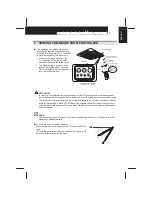
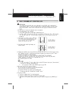
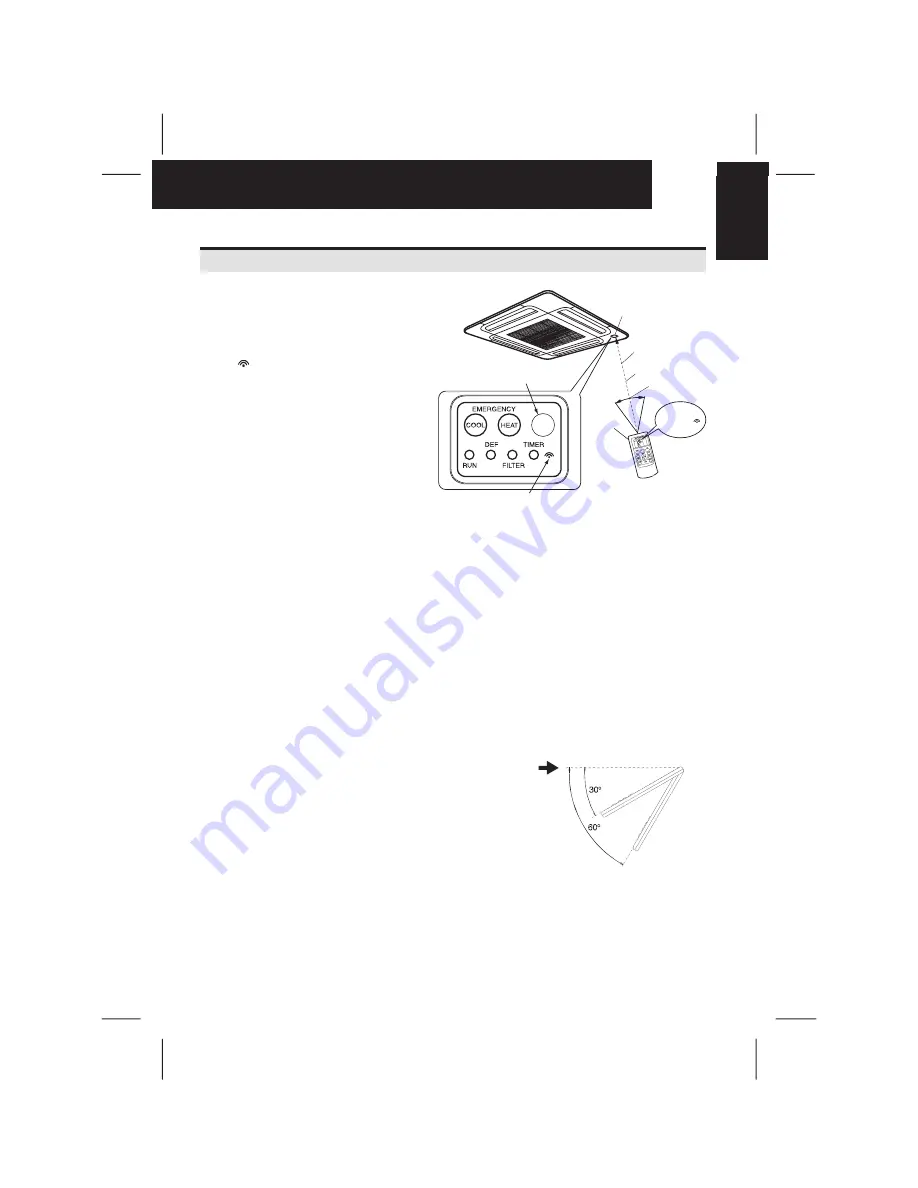
SENDING COMMANDS FROM CONTROLLER
The operation commands are sent by
pressing the required operation switch
by facing the transmitter of the controller
toward the receiver of the indoor unit.
1 When the commands are sent, the
'
' indication on the liquid crystal
display of the controller flashes once.
2 The indication lamp (yellow) on the
receiver part of the indoor unit turns
ON for an instant when the indoor unit
receives the commands.
Ô
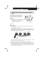
ATTENTION:
- In case that the indication lamp (yellow) does not turn ON although the commands are sent,
the commands are not received by the indoor unit. In such a case, send the commands again.
- The transmitter of the controller has the vertical directivity to the receiver, and the permissible
angle for transmitting is within 50
º
. However, the capable distance for transmitting gets half
when the transmitting angle is 50
º
, and also get shorter in case that an electronic type light is
used in the room.
NOTE:
The above figure shows the case of a 4-way cassette type indoor unit. The figures for other
models are different partially.
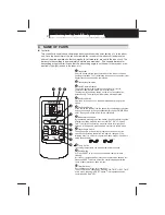
LCD (Liquid Crystal Display) Indication
When viewed from certain angles the LCD can be difficult to
read.
The viewing angle ranges from an optimal of 60º down to 30º,
as shown in the diagram on the right.
Receiver
Indication Lamp (Yellow)
turns ON for an instant
Receiver Part
Vertical Line between
transmiter and receiver.
Max. Distance for
transmitting 6m.
Within approx. 50°
(Directivity)
PC-LH3A
Transmitting
Indication
flashes once


