16
6. Wiring
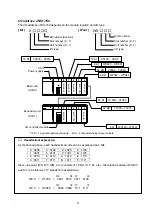
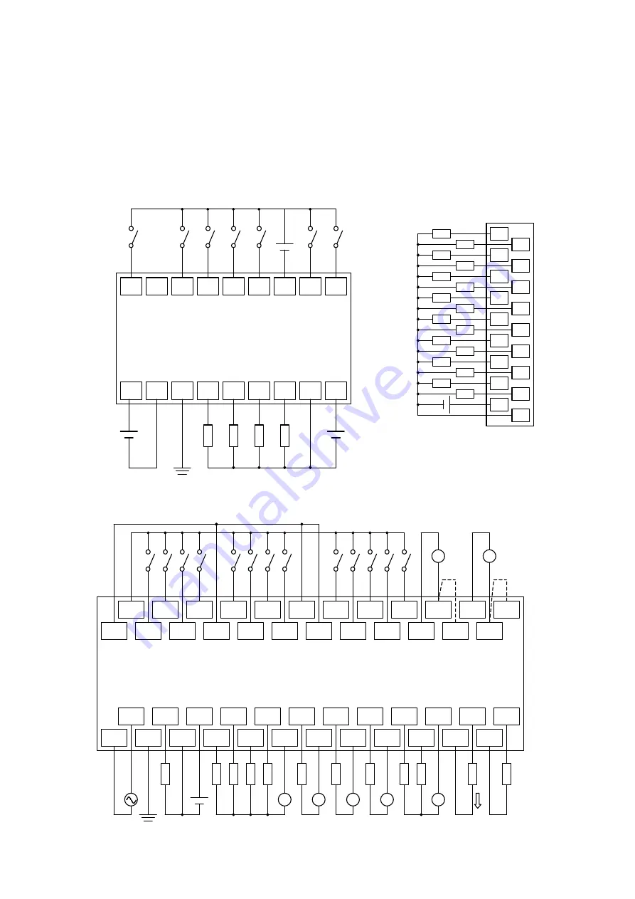
Wiring diagram for some modules are shown below. Implement wiring based on these drawings for
other MICRO-EH also. Each I/O module for EH-150 has a wiring label at the terminal block.
Note
: All DC inputs can be connected as either positive or negative logic.
24V
1
0
0V
3
4
C0
2
6
C1
7
5
8
10
9
C2
12
IN1+
IN1-
11
IN2-
IN2JP
IN2+
IN1JP
AC
0
GND
AC
V0
2
1
C0
4
5
C1
3
6
7
C3
C2
8
C5
9
C4
IO
VO
VC
IC
-
+
-
+
Connect jumper
in current mode
-
+
+
-
DC input
Analog input
Transistor
output
Relay output
Analog output
0
1
8
9
2
3
10
11
4
5
12
13
6
7
14
15
C
S
+
-
MICRO-EH [EH-D10DTP]
EH-150 [EH-YTP16]
MICRO-EH [EH-A23DRP]
RUN
NC
0
1
2
3
C0
4
5
-
+
DC input
Transistor output
-
+
24V
0V
GND
0
1
2
3
C0
V0
-
+
RUN input
CH 0 / CH 1
V / V : WRF06E = H0000
V / I : WRF06E = H4000
I / V : WRF06E = H8000
I / I : WRF06E = HC000

