3-21
[Setting of switch]
・
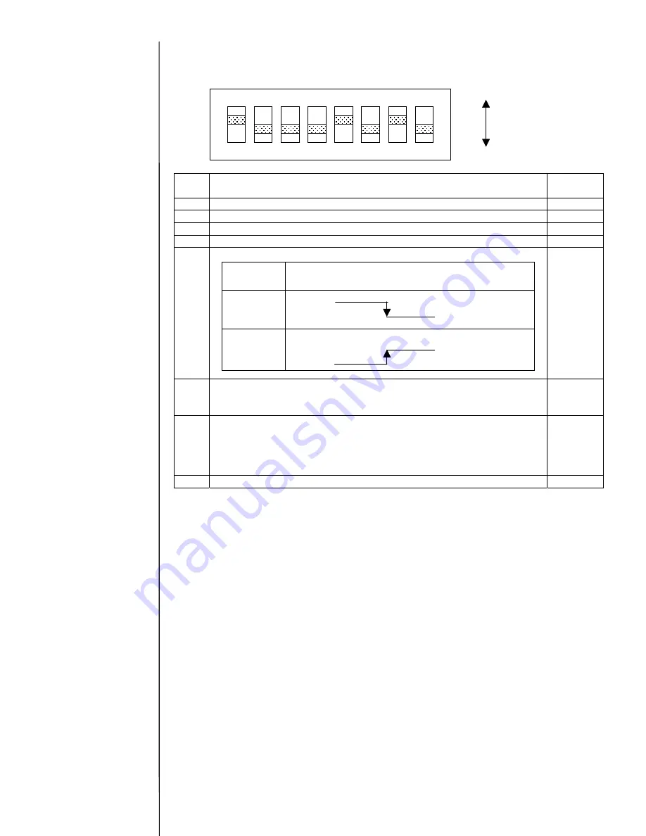
Setting of switch
[SW1]
SW1
Description
Standard
setting
Bit 1 Sets host communications (Set to ON)
ON
Bit 2 Sets host communications (Set to OFF)
OFF
Bit 3 Reserve (Set to OFF)
OFF
Bit 4 Reserve (Set to OFF)
OFF
Bit 5 Sets the polarity of strobe signal transmitted from host.
ON
Bit 6 Switches the filter constant of strobe signal (capacitance).
ON
:
0.047(uF)
+
2.2(uF)
OFF
:
0.047(uF)
OFF
Bit 7 Switches the power supply for input signal.
Set to ON when using the IJP internal power supply (12 V).
Set to OFF when using an external power supply
(Connect the external power supply (12- 24 V) to pin 1 of
terminal board (TB1).)
ON
Bit 8 Reserve (Set to OFF)
OFF
[Notes for replacement:]
- Be sure to turn power off when replacing the EZJ99 board.
- Save the data on memory card by using the copy data function before replacing the EZJ99
board, and be sure to recover the data after replacement.
As the operation management, the parts usage time management, password setup and the
unit information are not backed up by the copy data function. Set them again.
- Set the SW1.
OFF
ON
1
2
3
4
5
6
7
8
ON
Setting
Photo coupler operation
(voltage level at TB1 pin 12)
ON
O
FF
OFF
As for the copy data
function, see “2.9
Backup”.
Summary of Contents for PXR
Page 1: ...Service Manual HITACHI Printer Model PXR Revision December 2008 Version C ...
Page 80: ...3 17 3 17 Circuit diagram of EZJ95 ...
Page 215: ...8 2 8 1 2 Circulation system diagram PXR P ...
Page 216: ...8 2 Air system diagram PXR P 8 3 ...
Page 217: ...8 4 8 3 Electrical Connection Diagram 8 3 1 Electrical Connection Diagram PXR D ...
Page 218: ...8 5 8 3 2 Electrical Connection Diagram PXR H ...
Page 219: ...8 3 3 Electrical connection diagram PXR P 8 6 ...


