3
H
S
4
1
-
S
A
R
,
3
H
S
0
1
-
S
A
R
:
L
E
D
O
M
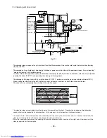
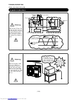
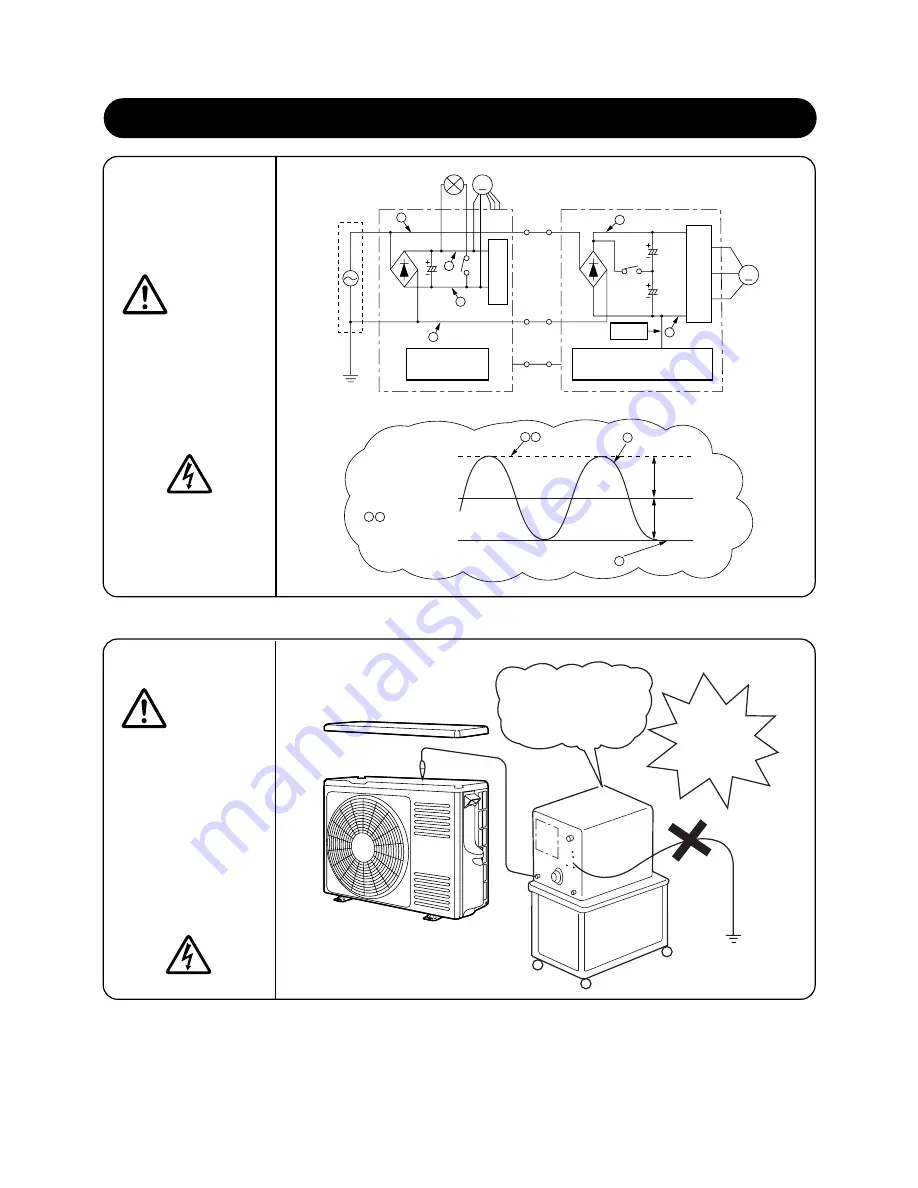
Note that the 0 V line of the
outdoor electrical parts and
the primary power circuit of
the indoor electrical parts
have voltages to ground as
illustrated in the right-hand
figure.
When conducting a check
with an oscilloscope or
something similar, do not
ground the oscilloscope.
Note that the oscilloscope
will be subjected to voltages
as illustrated in the figure
above.
TROUBLE SHOOTING
Warning
Warning
Power supply
Po
w
er circuit
Control circuit
Control circuit
Do not under any
circumstances get your
hand or metal part into
contact with the cabinet.
Danger!!!
Do not install
a grounding.
Inspection instructions
– 108 –
M
140V
140V
M
d
c
f
e
b
c
a
e
b
d
a
f
Two-way valve coil
Indoor fan motor
Outdoor electrical parts
Indoor
electrical
parts
Grounding
0V line
Relay
P
ow
er circuit
Compressor
motor
Voltage between each
part and ground
Grounding voltage
Potential at
points
Potential at
points
Potential at
points
Potential at points
Summary of Contents for RAC-10SH3
Page 57: ... 55 MODEL RAC 18SH3 Unit mm 580 5 600 345 299 19 5 ...
Page 60: ... 8 5 WIRING DIAGRAM MODEL RAS 10SH3 3 H S 4 1 S A R 3 H S 8 1 S A R INDOOR UNIT ...
Page 62: ... 0 6 MODEL RAC 18SH3 OUTDOOR UNIT WHT YEL RED INDOOR UNIT ...
Page 64: ... 2 6 3 H S 8 1 S A R 3 H S 4 1 S A R 3 H S 0 1 S A R L E D O M ...
Page 150: ... 8 4 1 MODEL RAC 18SH3 ...
Page 153: ...HHAW NO 0060E RAS 10SH3 RAC 10SH3 RAS 14SH3 RAC 10SH3 RAS 18SH3 RAC 18SH3 ...

