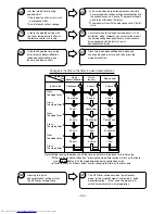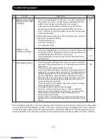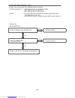
1. Failure phenomenon: The power will not become turned on.
[
Situation
]
Neither initialization, remote control, nor any other step works on the vane position at power-on.
[ Estimated failure
locations ]
・
3 A fuse blown out
・
Control power circuit
・
Connector loose, wire break
[
Cautions
]
[
Diagnosis flow
]
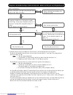
Initiating troubleshooting
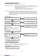
Is a voltage of 220 V AC applied between WR001 and
WR002?
Is the CN16 securely connected?
Replace the "indoor electrical parts".
Replace the "indoor electrical parts".
Replace the "3 A fuse".
Replace the "varistor (VA001)".
Abnormal
Is the power supply voltage normal?
Has the varistor VA001 not become burned?
Normal power supply voltage: 220 V AC
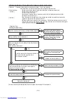
Estimated cause of fuse blowout
・
Abnormally high voltage applied to the power supply
・
Indoor fan motor out of order
・
Power circuit out of order
・
Before work, check the power supply voltage. An abnormal voltage may be being supplied in
some rare occasions due to a defect in the indoor wiring (a wire break in the neutral wire of the
single-phase 3-wire power supply).
・
If the 3 A fuse has blown out, eliminate the cause of the fuse blowout. Otherwise, there will occur
another fuse blowout.
・
If the 3 A fuse has blown out due to an abnormally high voltage to the power supply, the varistor
(VA001) will deteriorate and become destroyed as well.
・
On a repair service visit due to the failure phenomenon of "The power will not become turned on",
take a "3 A fuse" and a "varistor" with you.
Get the indoor wiring back to its
normal condition, then conduct
a final check.
Normal
No
No
No
No
Yes
Yes
Yes
Yes
Yes
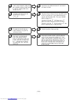
Replace the 3 A fuse, disconnect the CN2
(indoor fan motor), and conduct an operation
check. Has the product worked?
Replace the "indoor fan motor".
Another fuse blowout
Disconnect the CN2 and check for continuity
between the "red" and "black" wires of the
indoor fan motor by using a tester. Is it short-
circuited?
Apply the black lead of the tester to the red
lead of the motor. Apply the red lead of the
tester to the black lead of the motor.
Replace the "indoor electrical
parts".
Replace the "indoor fan motor".
Is 5 V DC applied to both ends of the C106?
Replace the "indoor electrical
parts".
Reconnect the connector correctly.
– 117 –
Summary of Contents for RAC-10SH3
Page 57: ... 55 MODEL RAC 18SH3 Unit mm 580 5 600 345 299 19 5 ...
Page 60: ... 8 5 WIRING DIAGRAM MODEL RAS 10SH3 3 H S 4 1 S A R 3 H S 8 1 S A R INDOOR UNIT ...
Page 62: ... 0 6 MODEL RAC 18SH3 OUTDOOR UNIT WHT YEL RED INDOOR UNIT ...
Page 64: ... 2 6 3 H S 8 1 S A R 3 H S 4 1 S A R 3 H S 0 1 S A R L E D O M ...
Page 150: ... 8 4 1 MODEL RAC 18SH3 ...
Page 153: ...HHAW NO 0060E RAS 10SH3 RAC 10SH3 RAS 14SH3 RAC 10SH3 RAS 18SH3 RAC 18SH3 ...


