– 91 –
2. Control power circuit
FM
K
A
R
I
G
O
AC220V
NF1
1 2 3 4
8
6
9
7
10
IC001
DB1
C003
D001
Primary 280V
RL003
C006
L151
D131
R134
D134
R135
C133
C13
1
R104
D133
R123
R13 2
C132
D132
C134
PC102
R236
IC681
12V
PC101
R10
2
R122
C101
T001
D101
D102
C126
C102
C103
R10
1
R10 3 C107
C127
IC102
R127
R128
R126
R129
C104
IC101
D103
C105
C106
12V
5V
0V
TH001
8.5V
10
57
7
V
A001
R002
C001
C002
Switching power circuit
Two-way
valve coil
Indoor fan
motor
FU1 3A fuse
Primary 0 V
Two-way valve
control circuit
Primary 18.5 V
Pin of microcomputer
Fig. 2-1
·
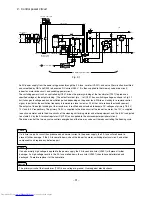
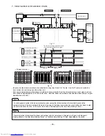
An AC power supply from the power plug passes through the 3 A fuse, varistor (VA001), and noise filter circuit and rectified
and smoothed by DB1 and C003 to become a DC current 280 V. It is then supplied to the two-way valve drive circuit,
indoor fan motor drive circuit, and switching power circuit.
·
The switching power circuit, as controlled by IC001, drives the primary winding of the transformer (T001) to produce a
specified voltage at the output winding. [The output terminal (pin
①
) of IC001 has a switching voltage as shown in Fig. 2-1
but it changes in voltage peak and oscillation period depending on the power load. While on standby for a remote control
signal, in particular, the oscillation frequency is lowered to a level as low as 20 kHz or so to reduce the standby power.]
·
The outputs of the output windings of the transformer is rectified and smoothed to become DC voltages at primary 18.5 V,
12 V, and 8.5 V respectively. The primary 18.5 V is supplied to the drive circuit of the indoor fan motor, the 12 V is supplied
to each vane motor and to the drive circuits of the cleaning unit driving motor and other equipment, and the 8.5 V is adjusted
to a stable 5 V by the 3-terminal regulator IC (IC101) and supplied to the microcomputer peripheral circuit.
·
The drive circuit of the two-way valve controls energization of the two-way valve coil, thereby controlling the freezing cycle.
If a failure in a part or circuit has produced an abnormal current in the power supply, the 3 A fuse will melt down to
prevent further damage. If the 3 A fuse melts down, check the indoor fan motor, switching electrical circuit, and other
components and replace any defective part.
If an abnormally high voltage is applied to the power supply, the 3 A fuse and varistor (VA001) will prevent further
damage. If a high voltage results in the 3 A fuse melted down, the varistor (VA001) should have deteriorated and
destroyed. Therefore replace it at the same time.
The primary circuit of the transformer (T001) has a voltage to ground. Guard against electric shocks.
Check
Check
Caution
Summary of Contents for RAC-10SH3
Page 57: ... 55 MODEL RAC 18SH3 Unit mm 580 5 600 345 299 19 5 ...
Page 60: ... 8 5 WIRING DIAGRAM MODEL RAS 10SH3 3 H S 4 1 S A R 3 H S 8 1 S A R INDOOR UNIT ...
Page 62: ... 0 6 MODEL RAC 18SH3 OUTDOOR UNIT WHT YEL RED INDOOR UNIT ...
Page 64: ... 2 6 3 H S 8 1 S A R 3 H S 4 1 S A R 3 H S 0 1 S A R L E D O M ...
Page 150: ... 8 4 1 MODEL RAC 18SH3 ...
Page 153: ...HHAW NO 0060E RAS 10SH3 RAC 10SH3 RAS 14SH3 RAC 10SH3 RAS 18SH3 RAC 18SH3 ...


