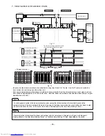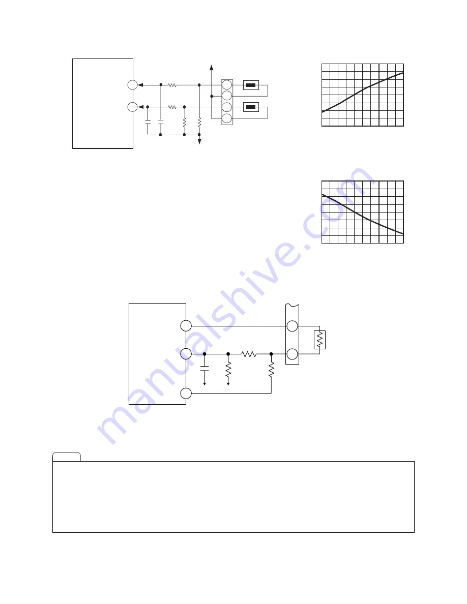
5. Room temperature heat exchanger thermistor circuit
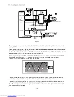
6. Humidity sensor circuit
C404
R403
R406
Microcomputer
IC601
Microcomputer
IC601
R407
C403
R402
Room temperature
thermistor
Heat exchanger
thermistor
Fig. 5-1
Fig. 5-2
Fig. 5-3
5V
0V
3
1
2
4
CN4
0
10
20
30
40
50
1.0
2.0
3.0
4.0
Thermistor temperature
(℃)
Thermistor temperature
(℃)
Thermistor characteristics
(microcomputer input voltage)
Room temperature
thermistor input
Heat exchanger
thermistor input
90
91
V
oltage (V)
Vo
ltage (V)
0
10
20
30
40
50
1.0
2.0
3.0
4.0
・
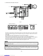
The room temperature and the temperature of the indoor heat exchanger pipe
are detected by using a thermistor.
・
A thermistor is a sensor whose resistance changes with the device temperature.
Analog voltages obtained by the resistance voltage divided with the fixed resistor
are recognized by the microcomputer (IC601) as temperature signals.
・
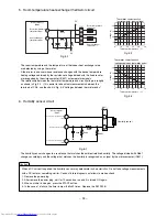
The relationship between the thermistor temperature and circuit voltage is roughly
as shown in Fig. 5-2. If it is easier to take actual measurements between the
terminals of CN4, use the chart in Fig. 5-3 "Voltages between thermistor ends."
Thermistor characteristics
(voltages between thermistor ends)
72
92
71
6
7
CN17
Humidity sensor input
Humidity sensor
R408
R409
C402
0V
0V
R661
Pulse output of humidity sensor
(P1)
Pulse output of humidity sensor
(P3)
Fig. 6-1
・
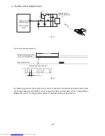
The humidity sensor changes to a resistance that matches the ambient relative humidity. The voltage divided with R661
changes accordingly and the voltage that matches the humidity is recognized as a signal by the microcomputer (IC601).
When a DC current is applied, the humidity sensor may deteriorate in characteristics. Do not take voltage measurements
with a DC tester or something similar. Conduct failure diagnosis as follows to make a check:
1. Remove the power plug.
2. After remove the power plug, wait for 10 seconds or so and it is turned ON again.
3. When an initial run begins, press the START button.
4. In the case of a failure, the timer lamp will blink 9 times. Replace the SW P.W.B.
Caution
– 94 –
Summary of Contents for RAC-10SH3
Page 57: ... 55 MODEL RAC 18SH3 Unit mm 580 5 600 345 299 19 5 ...
Page 60: ... 8 5 WIRING DIAGRAM MODEL RAS 10SH3 3 H S 4 1 S A R 3 H S 8 1 S A R INDOOR UNIT ...
Page 62: ... 0 6 MODEL RAC 18SH3 OUTDOOR UNIT WHT YEL RED INDOOR UNIT ...
Page 64: ... 2 6 3 H S 8 1 S A R 3 H S 4 1 S A R 3 H S 0 1 S A R L E D O M ...
Page 150: ... 8 4 1 MODEL RAC 18SH3 ...
Page 153: ...HHAW NO 0060E RAS 10SH3 RAC 10SH3 RAS 14SH3 RAC 10SH3 RAS 18SH3 RAC 18SH3 ...


