– 9 6 –
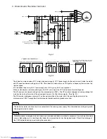
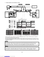
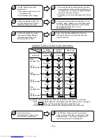
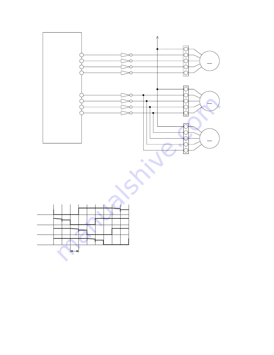
[Connector circuit waveform while the motor runs]
Voltage waveforms of different phases as viewed from
the OV line while the motor rotor is turning counterclockwise
as viewed from the shaft side
φ
4 terminal
φ
3 terminal
φ
2 terminal
φ
1 terminal
5 ms. or 10 ms.
Fig. 8-2
·
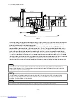
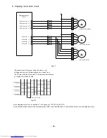
Each stepping motor runs as excited in 1 or 2 phases at 100 PPS or 200 PPS.
·
The excitation pattern passes the microcomputer (IC601) and then the driver IC and excites the coil of each stepping motor.
Vertical vane, left
-φ
4
Vertical vane, left
-φ
3
Vertical vane, left
-φ
2
Vertical vane, left
-φ
1
Lateral vane
-φ
1
Lateral vane
-φ
2
Lateral vane
-φ
3
Lateral vane
-φ
4
8. Stepping motor drive circuit
Microcomputer
Vertical vane motor
Lateral vane motor, left
Lateral vane motor, right
Fig. 8-1
1
12V
2
3
4
5
1
12V
2
3
4
5
1
2
3
4
5
CN15
CN12
24
23
22
21
73
74
75
76
CN9
12V
12V
IC601
φ
4
φ
3
φ
2
φ
1
φ
4
φ
3
φ
2
φ
1
φ
4
φ
3
φ
2
φ
1
M
M
M
Summary of Contents for RAC-10SH3
Page 57: ... 55 MODEL RAC 18SH3 Unit mm 580 5 600 345 299 19 5 ...
Page 60: ... 8 5 WIRING DIAGRAM MODEL RAS 10SH3 3 H S 4 1 S A R 3 H S 8 1 S A R INDOOR UNIT ...
Page 62: ... 0 6 MODEL RAC 18SH3 OUTDOOR UNIT WHT YEL RED INDOOR UNIT ...
Page 64: ... 2 6 3 H S 8 1 S A R 3 H S 4 1 S A R 3 H S 0 1 S A R L E D O M ...
Page 150: ... 8 4 1 MODEL RAC 18SH3 ...
Page 153: ...HHAW NO 0060E RAS 10SH3 RAC 10SH3 RAS 14SH3 RAC 10SH3 RAS 18SH3 RAC 18SH3 ...


