ENGLISH
– 11 –
HEA
TING OPERA
TION
ƽ
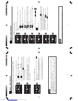
Use the device for heating when the outdoor temperature is under 21°C.
When it is too warm (over 21°C), the heating function may not work in order to protect the device.
ƽ
Press the MODE selector button so that the display indicates
(HEA
T).
Set the desired F
AN SPEED with the (F
AN SPEED) button
(the display indicates the setting).
Set the desired room temperature with the
TEMPER
A
TURE button
s
(the display indicates the setting).
The temperature setting and the actual room temperature may
vary depending on conditions.
Press the
(ST
AR
T/ST
OP) button. Heating operation starts with
a beep. Press the button again to stop operation.
Ƶ
Ƶ
During
AUT
O fan, the fan speed automatically changes as below:
ƽ
When the di
fference between room temperature and setting temperatur
e
is large, fan starts to run at HI speed.
ƽ
After room temperature reaches the preset temperature, fan speed
will be changed to lower speed to obtain optimum room temperature
condition for natural healthy heating.
ST
ART
ST
OP
Ƶ
Defrosting
Defrosting will be performed about once an hour when frost forms on the heat exchange of the outdoor unit,
for 5~10 minutes each time.
During defrosting operation, the operation lamp blinks in a cycle of 3 seconds on and 0.5 second of
f.
The maximum time for defrosting is 20 minutes.
(If the piping length used is longer than usual, frost is likely to form.)
1
2
3
In
order
to maintain reliability of the device, please use this device when outdoor temperature is above -15°C.
(AUT
O)
(HIGH)
(MED)
(LOW)
(SILENT)
Ƶ
As the settings are stored in the memory of the remote controller, you only
have to press the (ST
AR
T/ST
OP) button next time.
However, if the indoor unit is connected to multi type outdoor unit, the maximum time for defrosting is 15 minutes.
– 10 –
AUTOMA
TIC OPERA
TION
The device will automatically determine the mode of operation, HEA
T
or COOL
depending on the current
room temperature.
The selected mode of operation will change when the room temperature varies.
However
, the mode of operation will not change when indoor unit is connected to multi type outdoor unit.
V
ARIOUS FUNCTIONS
Ƶ
Auto Restart Control
ƽ
If there is a power failure, operation will be automatically restarted when the power is resumed with previous operation
mode and airflow direction.
(As the operation is not stopped by remote controller
.)
ƽ
If you intend not to continue the operation when the power is resumed, switch of
f the power supply
.
When you switch on the circuit breaker
, the operation will be automatically restarted with previous operation mode
and air flow
direction.
Note:
1. If you do not require
Auto Restart Control, please consult your sales agent.
2. Auto Restart Control is not available when
T
imer or Sleep
T
imer mode is set.
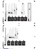
Press the MODE selector button so that the display indicates the
(AUT
O) mode of operation.
ƽ
When
AUT
O has been selected, the device will automatically
determine the mode of operation, HEA
T
or COOL
depending on
the current room temperature. However the mode of operation will
not change when indoor unit is connected to multi type outdoor
unit.
ƽ
If the mode automatically selected by the unit is not satisfactory
,
manually change the mode setting (HEA
T
, DEHUMIDIFY
, COOL
or F
AN).
Press the
(F
AN SPEED) button to select
AUT
O, HI, MED, LOW or
SILENT
.
Press the
(ST
AR
T/ST
OP) button.
Operation starts with a beep.
Press the button again to stop operation.
Set the desired room temperature with the
TEMPERA
TURE buttons
(the display indicates the setting).
The temperature setting and the actual room temperature may vary
depending on conditions.
ST
ART
ST
OP
1
3
2
Set the desired F
AN SPEED with the
(F
AN SPEED) button (the
display indicates the setting).
(AUT
O)
(HIGH)
(MED)
(LOW)
(SILENT)
Ƶ
As the settings are stored in
th
e memory
the remote controller
, you
(ST
AR
T/ST
OP) button next time.
only have to press the
of
12
Summary of Contents for RAC-25FPA
Page 2: ... DANGER 2 ...
Page 32: ...WIRING DIAGRAM OF THE PRINTED WIRING BOARD Remote controller RAR 5E2 32 ...
Page 33: ...MODEL RAF 25RPA RAC 35RPA 33 ...
Page 34: ...MODEL RAC 25FPA RAC 35FPA 34 ...
Page 39: ...39 ...
Page 41: ...41 ...
Page 44: ...44 ...
Page 59: ...10 10 10 10 R921 R924 R642 R544 R542 R610 R922 DSW1 DSW1 R923 R541 R543 100 59 ...
Page 77: ... 3 3 1 77 ...
Page 82: ...SELF DIAGNOSIS LIGHTING MODE MODEL RAC 25 A RAC 35 A FP FP 82 ...
Page 98: ...98 36 ...
Page 99: ...99 ...
Page 100: ...100 59 ...
Page 101: ...101 ...
Page 113: ...38 39 PARTS LIST AND DIAGRAM INDOOR UNIT MODEL RAF 25 35RPA 113 ...
Page 114: ...114 HWRAF 50NX2 A14 HBOARD AS ...
Page 117: ...RAF 25RPA RAC 25FPA RAF 35RPA RAC 35FPA HHAW NO 0069E 117 2 ...


