– 49 –
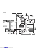
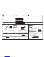
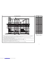
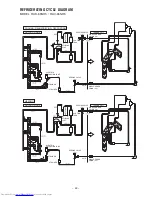
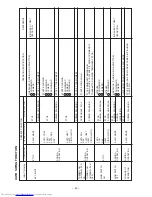
Reversing valve (heating “on” mode)
NOTE (9)
Notes:
(1) Condition for entering into Cool Dashed mode. When fan set to “Hi” or “Auto mode” and temperature difference between indoor temperature and set temperature has a
corresponding compressor rpm (calculated value in Table 2) larger than WMAX.
(2) Cool Dashed will release when i) a maximum 25 minutes is lapsed and ii) room temperature is lower than set temperature –3
°
C (thermo off) and iii) when room temperature
has achieved setting temperature –1
°
C then maximum Cool Dashed time will be revised to 20 minutes. And iv) indoor fan is set to Lo and Med fan mode and v) change operation
mode.
(3) During Cool Dashed operation, thermo off temperature is set temperature (with shift value) –3
°
C. After thermo off, operation continue in Fuzzy control mode.
(4) Compressor minimum “ON” time and “OFF” time is 3 minutes.
(5) During normal cooling mode, compressor maximum rpm CMAX will maintain for 60 minutes if indoor temperature is lower than CLMXTP. No time constrain if indoor temperature
is higher than CLMXTP.
(6) When fan is set to “Hi”, compressor rpm will be limited to CKYMAX.
(7) When fan is set to “Med”, compressor rpm will be limited to CJKMAX.
(8) When fan is set to “Lo”, compressor rpm will be limited to CBEMAX.
(9) During Cool Dashed, when room temperature reaches set temperature –1
°
C compressor rpm is actual rpm x DWNRATEC.
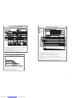
Temperature
Calculated
difference
compressor rpm
1.66
2265 min
–1
2
2435 min
–1
2.33
2600 min
–1
2.66
2765 min
–1
3
2935 min
–1
3.33
3100 min
–1
3.66
3265 min
–1
4
3435 min
–1
4.33
3600 min
–1
4.66
3765 min
–1
5
3935 min
–1
5.33
4100 min
–1
5.66
4265 min
–1
6
4435 min
–1
6.33
4600 min
–1
6.66
4765 min
–1
7
4935 min
–1
7.33
5100 min
–1
7.66
5265 min
–1
8
5435 min
–1
8.33
5600 min
–1
8.66
5765 min
–1
9
5935 min
–1
9.33
6100 min
–1
9.66
6265 min
–1
10
6435 min
–1
10.33
6600 min
–1
10.66
6765 min
–1
11
6935 min
–1
Table 2
∆
TCMAX
Note:
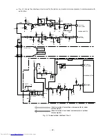
1. See the data in Table 1 on
page 47 for each constant in
capital letters in the diagrams.
Summary of Contents for RAC-65NH5
Page 36: ...CIRCUIT DIAGRAM 37 ...
Page 37: ...CIRCUIT DIAGRAM MODEL RAC 65NH5 39 ...
Page 87: ... 99 SELF DIAGNOSIS LIGHTING MODE ...
Page 89: ... 101 2 Outdoor unit does not operate but receives remote infrared signal ...
Page 91: ... 103 6 Check the main P W B power circuit ...
Page 92: ... 104 CHECKING THE REMOTE CONTROLLER ...
Page 97: ... 109 ...
Page 107: ...HITACHI PM NO 0000E Printed in Malaysia RAK 65NH5 RAC 65NH5 ...


