– 64 –
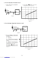
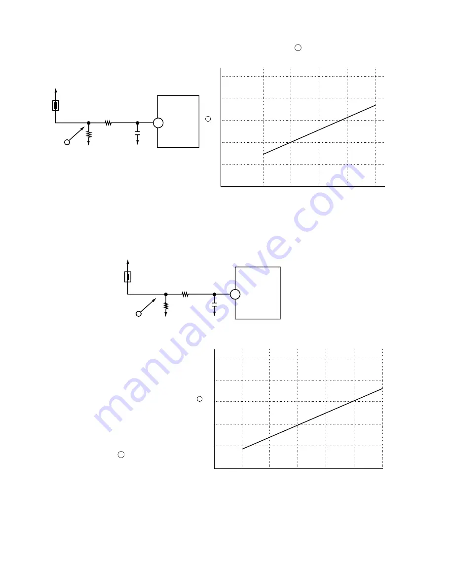
5. Room Temperature Thermistor Circuit
●
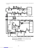
Fig. 5-1 shows the room temperature
thermistor circuit.
5
4
3
2
1
0
0
10
Room temperature (˚C)
Fig. 5-2
20
30
40
0V
Room
temperature
thermistor
0V
5V
Fig. 5-1
62
A
R305
C302
Microcomputer
Room
temp. input
V
oltage at
(V)
R301
0V
Heat exchanger
temperature thermistor
0V
5V
Fig. 6-1
61
A
R306
C303
Microcomputer
Heat
exchanger
temperature
input
R302
A
5
4
3
2
1
0
0
10
-10
Heat exchanger temperature (˚C)
Fig. 6-2
20
30
40
V
oltage at
(V)
A
6. Heat exchanger temperature thermistor circuit
●
The voltage at depends on the room
temperature as shown in Fig. 5-2.
●
The circuit detects the indoor heat
exchanger temperature and controls
the following.
(1)
Preheating.
(2)
Low-temperature defrosting
during cooling and dehumidifying
operation.
(3)
Detection of the reversing valve
non-operation or heat exchanger
temperature thermistor open.
The voltage at depends on the
heat exchanger temperature as shown
in Fig. 6-2.
A
A
Summary of Contents for RAC-65NH5
Page 36: ...CIRCUIT DIAGRAM 37 ...
Page 37: ...CIRCUIT DIAGRAM MODEL RAC 65NH5 39 ...
Page 87: ... 99 SELF DIAGNOSIS LIGHTING MODE ...
Page 89: ... 101 2 Outdoor unit does not operate but receives remote infrared signal ...
Page 91: ... 103 6 Check the main P W B power circuit ...
Page 92: ... 104 CHECKING THE REMOTE CONTROLLER ...
Page 97: ... 109 ...
Page 107: ...HITACHI PM NO 0000E Printed in Malaysia RAK 65NH5 RAC 65NH5 ...

