– 82 –
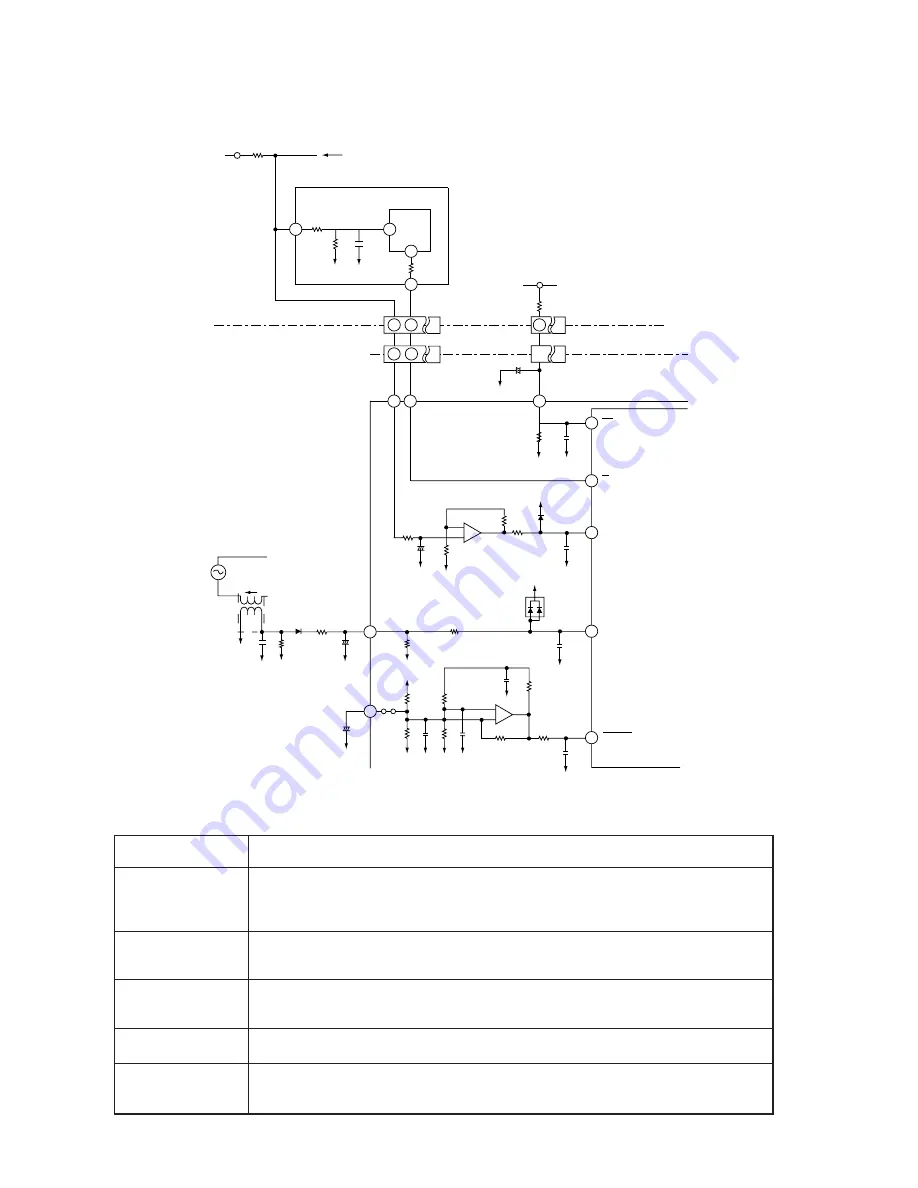
8. HIC and Peripheral Circuits
●
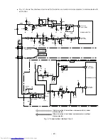
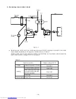
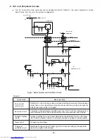
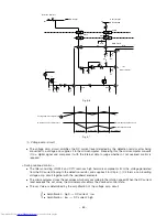
Fig. 8-1 shows the micro computer and its peripheral circuits, Table 8-1, the basic operations of each
circuit block, and Fig. 8-2, the system configuration.
Table 8-1
Circuit block
Basic operation
Peak current
cutoff circuit
Set value circuit
Voltage amplifier
circuit
Reset circuit
Trip signal
synthesis circuit
Detects DC current flowing power module and during overcurrent (instantaneous
value) flows, stops upper/lower arm drive circuits and also produces lp signal by
which drive signal output is stopped.
Compares voltage detected, amplified and input to HIC with set voltage value in
microcomputer, and controls overload when set value exceeds input voltage.
Voltage-amplifies DC current level detected by the detection resistor and inputs
this to microcomputer. Internal or external overload is judged in microcomputer.
Produces reset voltage.
Modulates chopper signal to drive signal and stops according to presence/ab-
sence of lp signal or reset signal.
59
17
61
48
58
62
+
+
60
Is
D104
L
CT1
N
R005
0V
0V
0V
0V
R221
C218
12V
R292
R247
C107
0V
0V
R006
C105
+
+
C217
C009
JW10
R252
R222
R248
IC4
C205
R288
IC5
+
–
2
3
1
+
–
6
5
7
Fig. 8-1 Microcomputer and Peripheral Circuits
RESET
Is
Id
Ip
Vd
CN13
CN14
R41
R24
N1
IC1
SPM2 – HIC
DC260-380V
P2
SPM2
MAIN P.W.B
Direct Current
DC Current
Detection Resistor
OC
F
0V
0V
HIC
IC1
C226
0V
R285
R286
D205
D204
R249
R284
0V
C225
C224
0V
0V
C222
0V
0V
C204
0V
C215
R289
0V
0V
5V
5V
R253
R500
R42
R43
C34
37
5
2
1
1
9
20
8
9
9
10
39
38
MICROCOMPUTER
0V
R245
Summary of Contents for RAC-65NH5
Page 36: ...CIRCUIT DIAGRAM 37 ...
Page 37: ...CIRCUIT DIAGRAM MODEL RAC 65NH5 39 ...
Page 87: ... 99 SELF DIAGNOSIS LIGHTING MODE ...
Page 89: ... 101 2 Outdoor unit does not operate but receives remote infrared signal ...
Page 91: ... 103 6 Check the main P W B power circuit ...
Page 92: ... 104 CHECKING THE REMOTE CONTROLLER ...
Page 97: ... 109 ...
Page 107: ...HITACHI PM NO 0000E Printed in Malaysia RAK 65NH5 RAC 65NH5 ...

