– 88 –
10. Reset Circuit
●
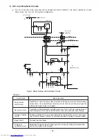
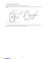
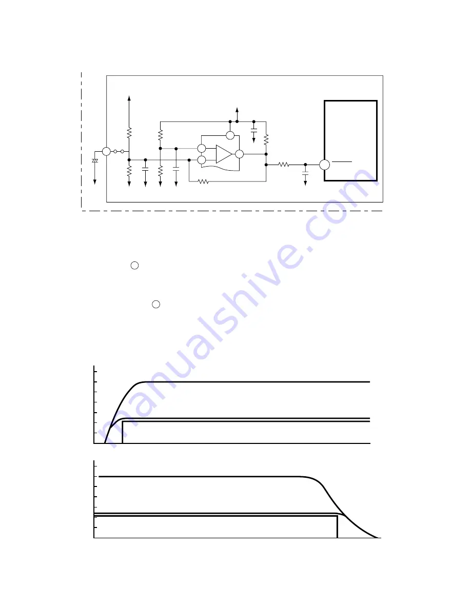
The reset circuit initializes the microcomputer program when Power is “ON” or “OFF”.
●
Low voltage at pin
48
resets the microcomputer, and HI activates the microcomputer.
●
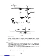
Fig. 10-1 shows the reset circuit and Fig. 10-2 shows waveform at each point when power is turned on
and off.
●
When power is turned on, 12V line and 5V line voltages rise and 12V line voltage reaches 10.9V and
reset voltage input to pin
48
of microcomputer is set to Hi.
●
Reset voltage will be hold “Hi” until the 12V line voltage drops to 9.90V even though the power shuts down.
Microcomputer
R252
R289
0V
0V
R288
0V
5V
12V
HIC
R284
JW10
IC5 (1/2)
C204
48
RESET
Main
P.W.B
Fig. 10-1
C215
R286
C225
C107
C226
R285
0V
1
3
2
62
8
–
+
+
0V
0V
R292
12V line
12V line
5V line
5V line
Fig. 10-2
Reset voltage
Reset voltage
12
6
0
Power is ON
V
oltage (V)
12
6
0
Power is OFF
V
oltage (V)
Time
Time
Summary of Contents for RAC-65NH5
Page 36: ...CIRCUIT DIAGRAM 37 ...
Page 37: ...CIRCUIT DIAGRAM MODEL RAC 65NH5 39 ...
Page 87: ... 99 SELF DIAGNOSIS LIGHTING MODE ...
Page 89: ... 101 2 Outdoor unit does not operate but receives remote infrared signal ...
Page 91: ... 103 6 Check the main P W B power circuit ...
Page 92: ... 104 CHECKING THE REMOTE CONTROLLER ...
Page 97: ... 109 ...
Page 107: ...HITACHI PM NO 0000E Printed in Malaysia RAK 65NH5 RAC 65NH5 ...

