– 96 –
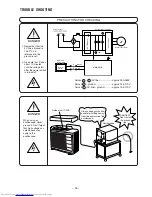
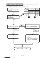
1. Turn OFF the Power supply to the outdoor unit.
2. After power is turned off, wait for 10 minutes or more. Then, remove electrical parts cover and apply soldering
iron of 30 to 75W for 15 seconds or more to P2 and N1 terminals on system power module, in order to
discharge voltage in smoothing capacitor.
3. Remove receptable of red/gray lead wire connected to system power module from diode stack before
performing operation chech of each circuit.
Caution
●
Voltage of about 300-330V is charged between both ends of smoothing capacitors
●
During continuity check for each part of circuit in indoor unit electrical parts, disconnect red/gray
lead wire connected from diode stack to system power module (SPM2) to prevent secondary
trouble. (Be sure to discharge smoothing capacitor)
Do not use a soldering iron with
transformer: If one is used, thermal fuse
inside transformer will be blown
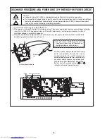
DISCHARGE PROCEDURE AND POWER SHUT OFF METHOD FOR POWER CIRCUIT
WARNING
As shown above, apply soldering iron to metal
parts (receptable) inside the sleeve
corresponding to P1 and N1 terminals of
system power module: Do this with smoothing
capacitors kept connected. By removing red/
gray lead wire from diode stack, power supply
can be shut off. (corresponding to + and –
terminals of system power module)
N1
P1
Soldering
iron
System power module
SPM2
Smoothing capacitors
Summary of Contents for RAC-65NH5
Page 36: ...CIRCUIT DIAGRAM 37 ...
Page 37: ...CIRCUIT DIAGRAM MODEL RAC 65NH5 39 ...
Page 87: ... 99 SELF DIAGNOSIS LIGHTING MODE ...
Page 89: ... 101 2 Outdoor unit does not operate but receives remote infrared signal ...
Page 91: ... 103 6 Check the main P W B power circuit ...
Page 92: ... 104 CHECKING THE REMOTE CONTROLLER ...
Page 97: ... 109 ...
Page 107: ...HITACHI PM NO 0000E Printed in Malaysia RAK 65NH5 RAC 65NH5 ...

