– 98 –
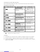
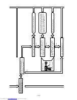
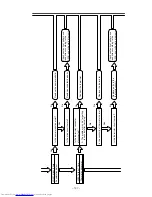
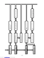
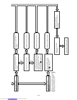
TROUBLESHOOTING WHEN TIMER LAMP BLINKS.
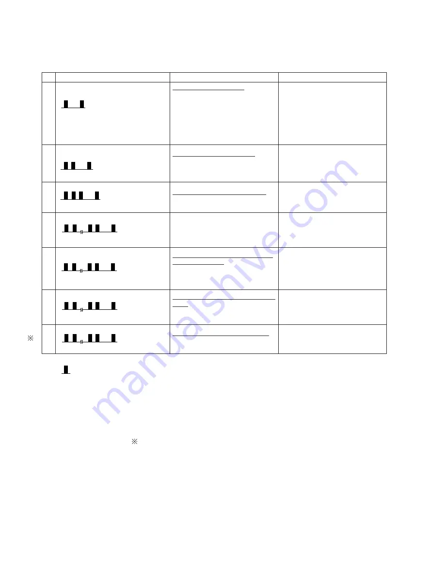
Perform troubleshooting according to the number of times the indoor timer lamp and outdoor LD301 blink.
SELF-DIAGNOSIS LIGHTING MODE
No.
Blinking of Timer lamp
Reason for indication
Possible cause
Reversing valve defective
When the indoor heat exchanger
temperature is too low in the
heating mode or it is too high in the
cooling mode.
Outdoor unit forced operation
When the outdoor unit is in forced
operation or balancing operation
after forced operation
Indoor/outdoor interface defective
When the interface signal from the
outdoor unit is interrupted.
Outdoor electrical assembly
defective.
Room thermistor or heat exchanger
thermistor is faulty
When room thermistor or heat
exchanger thermistor is opened
circuit or short circuit.
Over-current detection at the DC fan
motor
when over-current is detected at the
DC fan motor of the indoor unit.
IC401 or IC402 data reading error
When data read from IC401 or
IC402 is incorrect.
(1) Reversing valve defective
(2) Heat exchanger thermistor dis-
connected
(only in the heating mode)
(Note)
The malfunction mode is entered the
3rd time this abnormal indication
appears (read every 3 minutes).
Electrical parts in the outdoor unit
(1) Indoor interface circuit
(2) Outdoor interface circuit
Please check at the outdoor
electrical led lamp blinking (LD301)
and refer to self diagnosis lighting
mode for outdoor unit.
(1) Room thermistor
(2) Heat exchanger thermistor
(1) Indoor fan locked
(2) Indoor fan motor
(3) Indoor control P.W.B.
IC401 or IC402 abnormal
<Cautions>
(1)
If the interface circuit is faulty when power is supplied, the self-diagnosis display will not be displayed.
(2)
If the indoor unit does not operate at all, check to see if the F-cable is connected or disconnected.
(3)
To check operation again when the timer lamp is blinking, you can use the remote control for operation
(except for mode mark 1).
1
2
3
4
5
6
7
( – – Lights for 0.5 sec. at interval of 0.5 sec..)
– – 10 times
– – – – – – 3 times
– – – – – – – – 1 time
– – – – – – – 2 times
– – 13 times
1
– – 9 times
– – 4 times
5 sec.
5 sec.
5 sec.
5 sec.
5 sec.
5 sec.
5 sec.
5 sec.
Summary of Contents for RAC-65NH5
Page 36: ...CIRCUIT DIAGRAM 37 ...
Page 37: ...CIRCUIT DIAGRAM MODEL RAC 65NH5 39 ...
Page 87: ... 99 SELF DIAGNOSIS LIGHTING MODE ...
Page 89: ... 101 2 Outdoor unit does not operate but receives remote infrared signal ...
Page 91: ... 103 6 Check the main P W B power circuit ...
Page 92: ... 104 CHECKING THE REMOTE CONTROLLER ...
Page 97: ... 109 ...
Page 107: ...HITACHI PM NO 0000E Printed in Malaysia RAK 65NH5 RAC 65NH5 ...


