– 100 –
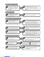
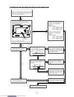
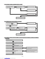
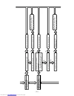
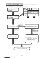
1. Power does not come on (no operation)
Is AC 220-240V AC being generated
between terminals L and N on the
outdoor unit terminal board?
Is DC 35V being generated between
terminals C and D on the outdoor
unit terminal board?
Check the indoor/outdoor unit
connection cable, and correct any
defective section (wrong connection,
incomplete insertion reversed).
Check AC outlet and breaker, and
repair any defective part.
Check the outdoor unit power circuit,
and repair the defective section.
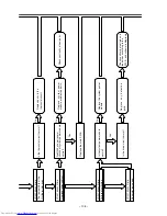
Is DC 35V being generated between
terminals C and D on the terminal
board?
Are control voltages (12V, 5V)
being generated normally?
Check according to the proper method
for checking the power circuit.
No
No
No
No
Yes
Yes
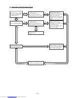
Do the air deflectors perform initial
operation when the power supply is
turned on and off?
Check the indication P.W.B.
connection cord and light receiving
unit.
No
No
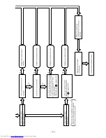
Is the microcomputer reset input
(pin 7 )“Hi” ?
Replace the control P.W.B
Perform final operation check.
Check the reset circuit, and repair
any defective section.
Yes
No
Is the microcomputer clock signal
10MHz at pin
10
11
being
generated normally?
Replace the microcomputer and
oscillator.
Yes
Yes
Yes
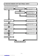
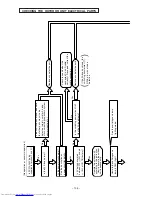
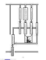
CHECKING INDOOR UNIT ELECTRICAL PARTS
Summary of Contents for RAC-65NH5
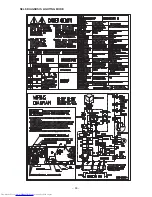
Page 36: ...CIRCUIT DIAGRAM 37 ...
Page 37: ...CIRCUIT DIAGRAM MODEL RAC 65NH5 39 ...
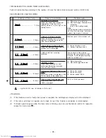
Page 87: ... 99 SELF DIAGNOSIS LIGHTING MODE ...
Page 89: ... 101 2 Outdoor unit does not operate but receives remote infrared signal ...
Page 91: ... 103 6 Check the main P W B power circuit ...
Page 92: ... 104 CHECKING THE REMOTE CONTROLLER ...
Page 97: ... 109 ...
Page 107: ...HITACHI PM NO 0000E Printed in Malaysia RAK 65NH5 RAC 65NH5 ...

