– 106 –
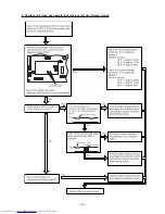
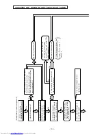
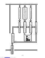
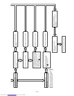
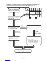
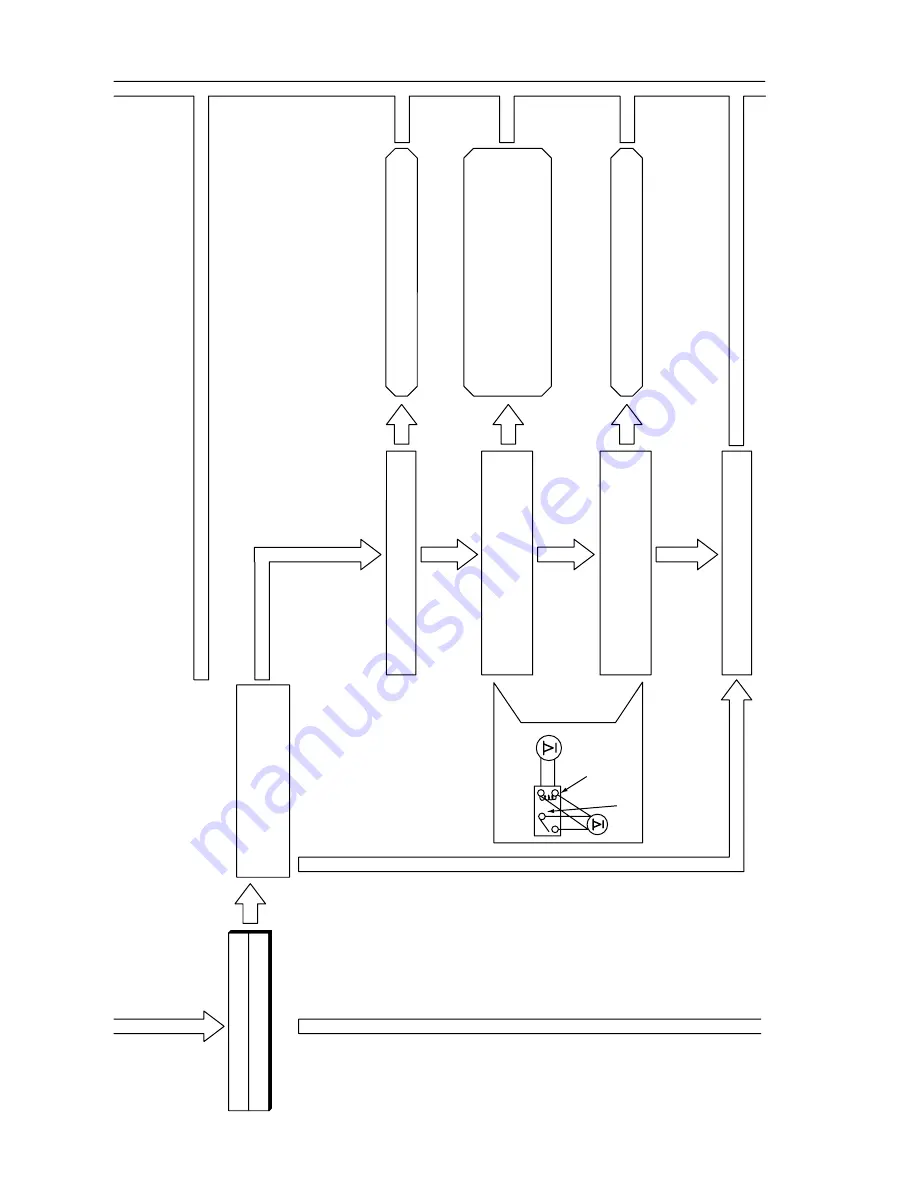
LD301 blinks 9 time.
Communication error
.
Is DC 35V being output at
terminals C and D? (Normally
,
DC 33-38.5V is output.)
Ye
s
Interface relay
Coil terminal
Contact terminal
Is DC 35V being output across R914?
Is DC 12V being supplied across
the control side (coil terminal) of
interface relay?
Is a voltage (at least 10V) being
generated between the contact
terminals of interface relay?
Check the interface curcuit.
Ye
s
Ye
s
No
No
Ye
s
D907 and C910 may be defective.
There is a defective section between the
12V output of switching power supply on
the main P
.W
.B. and interface relay (also,
check for contact with solder
, etc.).
Repalce the interface relay
.
No
Summary of Contents for RAC-65NH5
Page 36: ...CIRCUIT DIAGRAM 37 ...
Page 37: ...CIRCUIT DIAGRAM MODEL RAC 65NH5 39 ...
Page 87: ... 99 SELF DIAGNOSIS LIGHTING MODE ...
Page 89: ... 101 2 Outdoor unit does not operate but receives remote infrared signal ...
Page 91: ... 103 6 Check the main P W B power circuit ...
Page 92: ... 104 CHECKING THE REMOTE CONTROLLER ...
Page 97: ... 109 ...
Page 107: ...HITACHI PM NO 0000E Printed in Malaysia RAK 65NH5 RAC 65NH5 ...


