Operation mode
1
→
2
→
3
→
4
→
5
→
6
→
7
→
8
VALVE CLOSE
8
→
7
→
6
→
5
→
4
→
3
→
2
→
1
VALVE OPEN
ON
1
ON
2
OFF
3
OFF
4
5
OFF OFF
6
OFF
7
ON
OFF ON
ON
ON OFF OFF OFF OFF
OFF OFF OFF ON
ON
ON OFF OFF
OFF OFF OFF OFF OFF ON
ON
ON
8
④
③
②
①
④
③
②
①
Connector
Pin No.
12V
0.9V
50ms.
75ms.
200ms.
Q401
Q402
Q403
Q404
+5V
R407
R408
R409
R410
R2
29
93
R295
R294
R296
R404
R403
PQ401
PQ402
PQ403
PQ404
9
4
3
1
2
14
C401
+
CN15
XA−6P
7
8
1
1
12
6
13
3
6
ⅠC6
2
10
0
5
4
15
B−0V
5
WHT
3
4
2
1
B−12V
55
5
57
58
8
56
13
15
16
14
H
Ⅰ
C
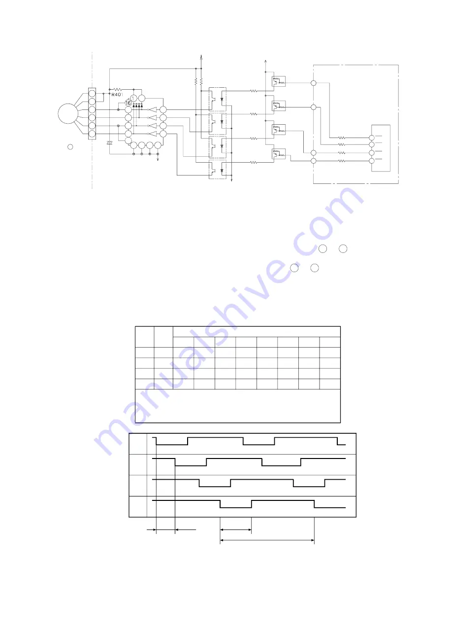
6-6. Electric expansion valve control circuit
Fig. 6-14
Main P.W.B.
Electric
expansion
valve
Microcomputer
Valve 4
Valve 3
Valve 2
Valve 1
●
Electric expansion valve is driven by B-12V. Opening of the valve is controlled by feeding power to 1
or 2 phases of the 4-phase coil to switch the polarity of the coil.
●
The relation between the conducting phase switching direction and open/close direction is as shown
below. When the power is turned on, approx. 0.9 V is applied to CN15 pins 1 to 4 ; when no power
is supplied, approx. 12 V is applied. When the power is reset, expansion valve performs initial
operation for 5 to 10 seconds.During initial operation, measure pins 1 to 4 of CN15 using
multimeter: If no change is found around 0.9 V or 12V, expansion valve or microcomputer is
defective.
●
Fig. 6-15 shows logic waveform during the operation of expansion valve.
Table 6-4
Fig. 6-15
CN 15
Pin No.
Lead
wire
Drive status
White
Yellow
Orange
Blue
1
24
53
46
45
44
HIC
- 64 -


