TROUBLE SHOOTING
PRECAUTIONS FOR CHECKING
MODEL RAC-E10H2
WARNING
WARNING
Always keep your hands
and metallic things away
from the cabinet.
DANGER!
Don't install
the ground
line.
When using an
oscilloscope, never
ground it.
Don't forget that high
voltage as noted in
the figure above may
apply to the
oscilloscope.
Remember that
voltage of 175 V is
applied to the 0V line
on the P.W.B. or the
like as shown in the
right diagram.
Indoor Controller
Outdoor Controller
Power Switch
Point
400 F
I.P.M
Compressor
motor
Point
line
Control
P.W.B.
Main P.W.B.
Voltage at point A
Ground voltage
Grounding
350V
Point B (0V line)
Power
inlet
WARNING
Do not use a soldering iron with
transformer: Otherwise, thermal fuse
inside transformer will be blown.
Caution
• Voltage of about 350
• V
• V
V is charged between the terminal of smoothing capacitors (375µF x 2).
• During continuity check for each circuit part of the outdoor unit, be sure to discharge the smoothing
capacitors.
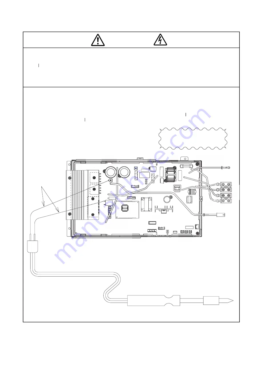
Discharge Procedure
1. Turn off the power of the indoor unit or pull out the power supply plug.
2. After power is turned off, wait for 10 minutes or more. Then, remove electrical parts cover
and apply soldering iron of 30 to 75 W for 15 seconds or more to TAB05 and R001
TT
terminals on the main P.W.
P.
P. B. as shown in the figure below, in order to dischargevoltage in
smoothing capacitor.
DISCHARGE, PROCEDURE AND POWER SHUT OFF METHOD FOR POWER CIRCUIT
LEAD WIRE
SOLDERING IRON (30 TO 75W)
- 71 -


