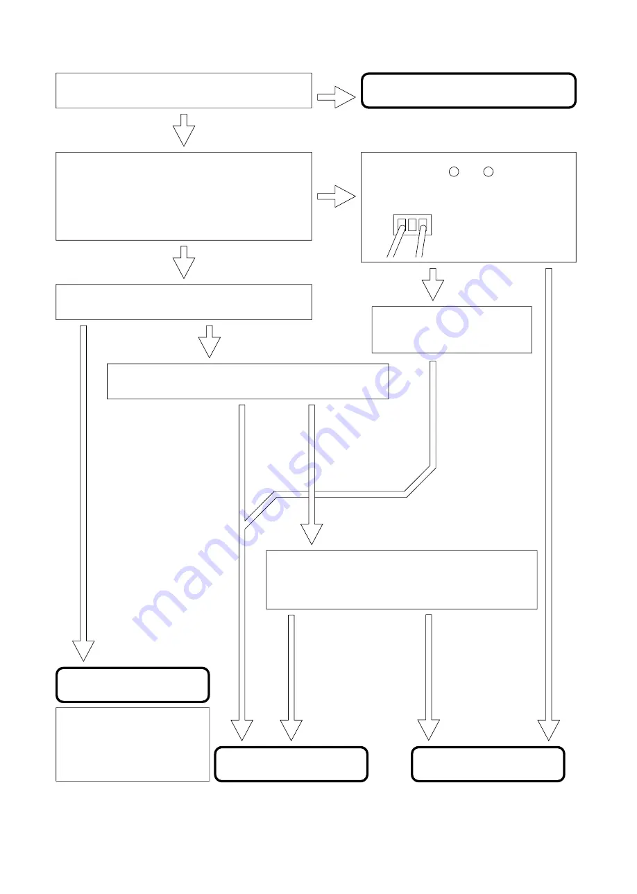
Is the indoor unit "timer lamp" blinking?
Yes
Yes
Yes
No
No
No
Trouble shoot according to the
self-diagnosis lighting mode.
Run the unit using the following remote controller settings:
In the cooling season, set the temperature to 16
℃
in the cooling
mode.
In the heating season, set the temperature to 32
℃
in the heating
mode.
Does the operation lamp light or blink?
Open the indoor unit and check the voltage
between pins Nos. 1 and 3 of CN3 on the
indoor unit control P.W.B.
Normal: DC35V (32-38V)
Red
Brown
Is the voltage correct?
Is the compressor running?
Check if the connecting cable
connected incorrectly? inserted
incompletely? or disconnected?
Not running
Running
Open the outdoor unit and observe the self-diagnosis
lamp (LD301). Count how many times the lamp blinks.
Blinks other than 1 time.
Blinks 1 time.
Can the unit be operated using the outdoor unit
service switch?
(See the nameplate on the outdoor unit for operating
instructions.)
Check the outdoor
electrical parts.
Check the indoor
electrical parts.
Check the refrigerating cycle.
In the event of overload limit cut or OH
thermistor temperature rise, use the
self-diagnosis memory function because
such failure may evade detection due to
ambient temperature variations or other
factors.
No
Yes
CHECKING THE INDOOR/OUTDOOR UNIT ELECTRICALPARTS AND REFRIGERATING
PA
PA
1. Power does not come on (no operation)
Is AC220-230V being generated between
terminals A and B on the indoor unit
terminal board?
Is AC220-230V being generated at AC
outlet?
Check AC outlet and breaker, and
repair any defective part.
Check the outdoor unit power circuit,
and repair any defective part.
Check according to the proper method
for checking the power circuit.
Check the reset circuit, and repair
any defective section.
Replace the microcomputer and
oscillator.
Is the control voltage being
generated normally?
12V line: 12V or 7V
5V line: 5V
Do the air deflectors perform initial
operation when the power supply is
turned on after off?
Check the power cable, power
switch, and terminal board, and
repair any defective part.
Check the indoor/outdoor unit
connection cable, and correct any
defective section (wrong connection,
incomplete insertion).
Is AC220-230V being generated between
terminals A and B on the outdoor unit
terminal board?
Is DC35V or 20V being generated
between terminals C and D on the
indoor unit terminal board?
Is the microcomputer reset input
(pin 7 ) "Hi"?
Is the microcomputer clock signal
generated normally?
Is DC35V is being generated between
terminals C and D on the outdoor unit
terminal board?
Are C and D connection cables
reversed?
Connect the cables correctly.
Check the wireless light receiving unit.
Replace the control P.W.B.
Perform final operation check.
25V - 20V
12V - 7V
Yes
Yes
Yes
Yes
Yes
Yes
Yes
Yes
Yes
Yes
No
No
No
No
No
No
No
No
No
No
1
10MHz at pins 10 and 11 being
1
: When not in operation, the unit will enter into a low-power standby state, possibly causing a voltage drop to the 12V and 35V lines
as shown below.
- 78 -


