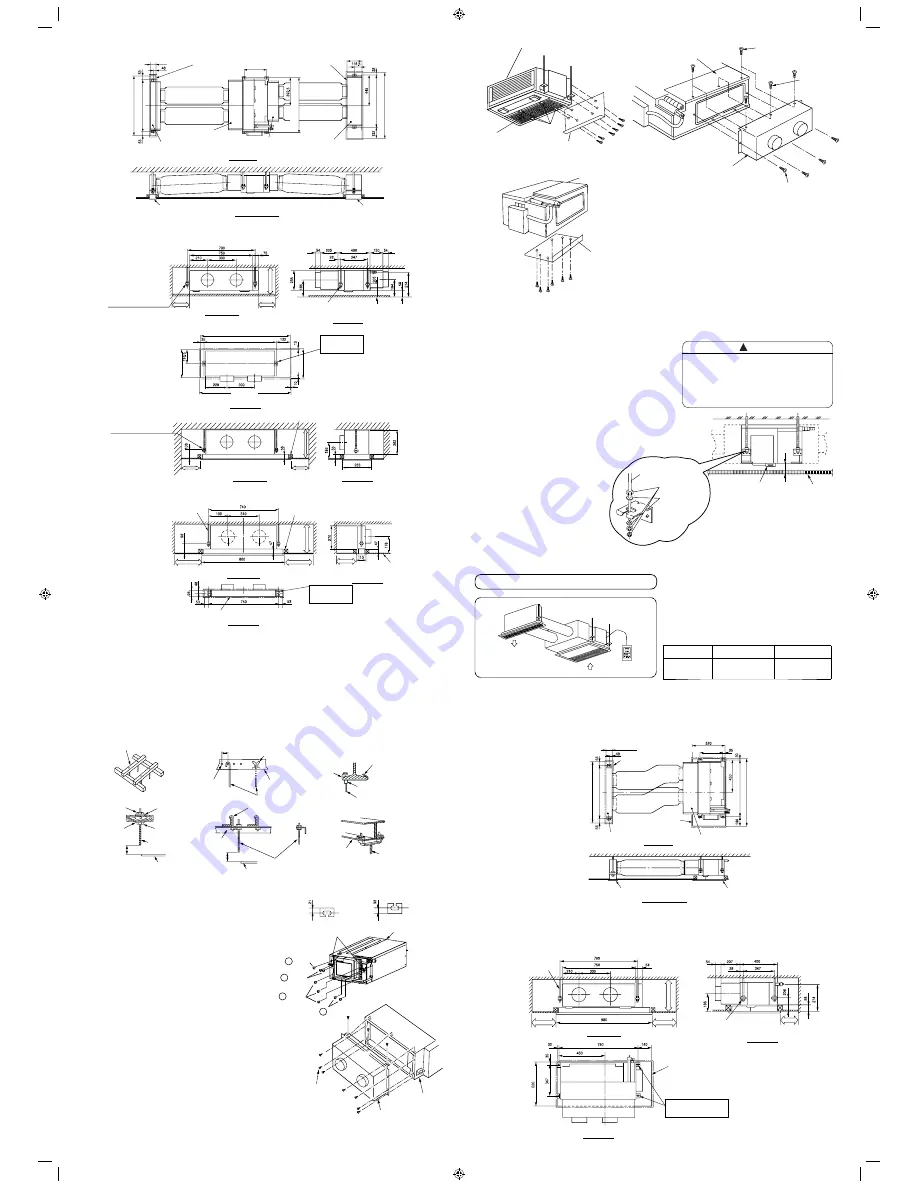
(5) Installation of indoor unit
• Set nut and washer on suspension bolt and hook it
to suspend clamp by lifting the indoor unit.
• Make sure that the indoor unit is leveled using a
level or vinyl hose with water.
• Fix the indoor unit so that the space between
bottom surfaces of ceiling and indoor unit is 58mm.
[Installation of chamber of suction grille]
[Installation of chamber of discharge grille]
[Installation of suction grille]
[Installation of discharge grille]
[Installation of flexible duct]
Refer to installation manual of optional part.
• Select the indoor unit position,
fi
xing direction of air
outlet so that cool/hot air reaches the entire room.
Standard position or the indoor unit is on wall side.
• Permissible length and bending of duct.
Permissible length
Bending
Discharging
side duct
4m or less
90° or less,
1 section
• Secure the space for installation, inspection or servicing.
• Apply waterproof treatment under the indoor unit to prevent water leak.
• Make sure that no obstacle is blocking the air
fl
ow within 1m of suction grille.
(1) Installation
fi
gure
(2) Opening on ceiling and suspension bolt position
•
Indoor unit
(1) Installation
fi
gure
(2) Opening on ceiling and suspension bolt position
• Indoor unit
•
Chamber of suction grille
•
Chamber of discharge grille
• Arrange drain pipe, refrigerant pipe, and connecting cord in their installation position.
• For
fi
nishing of opening on ceiling, arrange with builder in detail.
(3) Installation of suspension bolt
• Make sure to reinforce furring of ceiling (frame: ceiling joint and supporter) to maintain level of ceiling and
prevent vibration of ceiling plate.
• Suspension bolts should be purchased in the
fi
eld.
• Refer to diagrams shown below for length of suspension bolts.
(4) Preparation for installing indoor unit
• Remove the screw
of the electric box and then
remove electric box.
• Relocate the electric box with lead wires kept
connected. Ensure the lead wire is positioned at the
upper side, and hook the claw of electric box to the
bottom of the indoor unit using 4 screws.
• Install 4 suspension clamps at both sides of indoor unit,
2 clamps at each side, using 8 tapping screws
.
(Since size of left and right clamps are different for
certain parts, refer to diagram on the right.)
• Install chamber of discharge of unit side on the indoor
unit using 10 tapping screws.
• Remove the
fi
lter at the bottom side of indoor unit by
unscrew 8 screws at the
fi
lter holders. (4 portions)
• Remove 6 screws at back plate of indoor unit. Then
install the back plate at the bottom of indoor unit using
6 screws.
• Remove 2 screws at top plate of indoor unit and install
chamber of suction of unit side using 7 screws.
CAUTION
• Be sure to install the indoor unit level. If the
indoor unit is inclined, water may leak.
• If space between bottom surfaces of indoor
unit and ceiling is not correct, there may be a
gap between grille and ceiling surface, with
consequent leakage of condensed water.
!
•
In case of wooden frame
•
In case of steel frame
INSTALLATION OF SEMI DUCT TYPE
Opening on ceiling 96
Flexible duct
Flexible duct
Chamber of discharge grille
Cross section
Front view
Front view
Front view
Front view
Plan view
Plan view
Side view
Side view
Side view
Top view
Cross section
Plan view
Side view
Top view
Chamber of suction of unit side
Chamber of
suction grille
Chamber of discharge
of unit side
Opening on ceiling 864
Indoor unit
Suspension bolt 790
Suspension bolt 793
Opening on ceiling 960
Suspension bolt 740
Discharge opening size
(846 x 96)
Suction opening size
(960 x 233)
(Unit : mm)
(Unit : mm)
Suction grille
Discharge grille
Suspension bolt
(M10: Local purchase)
Suspension bolt
(M10: Local purchase)
Suspension bolt
(M10: Local purchase)
Reinforcement
Ceiling
Suspension bolt
(M10: Local purchase)
Above 300
Above 300
Above 300
Above 300
Opening on ceiling
60~90mm square piece of lumber
Nut
Reinforcing bar
C type metal
H beam
Nut
Ceiling
Ceiling
Suspension bolt
(M10)
Suspension bolt
(M10)
Suspension bolt (M10)
Suspension bolt (M10)
Suspension bolt (M10)
Indoor unit
Chamber of discharge
of unit side
Screw
Bend slip-preventive metal
Opening on ceiling 846
Opening on ceiling 960
Suspension bolt 790
Indoor unit
Suspension bolt 740
Angle
Angle
Angle
Hanger bolt
Concrete
Long nut
Insert
(100~150kg)
150~160mm
About 130
About 130
Above 200
Above 300
Opening on ceiling 960
Suspension bolt 793
Grille 980
Grille
253
Above 300
Reinforcement
Above 330
Above 330
Above 330
Opening on ceiling 233
Opening on ceiling 233
Indoor unit
Back plate
Back plate
Indoor unit
(1) Bottom side suction opening
(2) Back side suction opening
A level
Suspension bolt (M10)
(Local
purchase)
Hexagon nut (M10)
(Local
purchase)
Washer
(Local purchase)
58mm
Ceiling
Filter holders
Filter
Top plate
Remove the screw
Screws to fit
electric box
Chamber of suction of unit side
Screw
Suspension bolt 347
Suspension bolt
position 740
Suspension bolt
position 793
Opening on ceiling 96
Flexible duct
Flexible duct
Chamber of discharge of unit side
Suction grille
Suction opening size
(960 x 520)
Chamber of discharge grille
Above 300
Above 300
Above 200
Above 300
Discharge grille
Discharge opening size
(846 x 96)
Suspension bolt 347
Suspension bolt position
790 x 347
Suspension bolt
(M10: Local purchase)
Suspension bolt
(M10: Local purchase)
Opening on ceiling
(Unit : mm)
(Unit : mm)
Left side
suspension clamp (2)
Right side
suspension clamp (2)
Screw
3
Screw
8
Screw
3
Screw
8
INS RAD-18-25-35-50QPB (EN) 2
INS RAD-18-25-35-50QPB (EN) 2
12/19/14 9:42 AM
12/19/14 9:42 AM


