


9 Piping work and refrigerant charge
Copper pipes, sizes and connection
TCGB0136 rev.1 - 05/2021
90
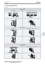
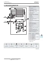
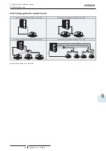
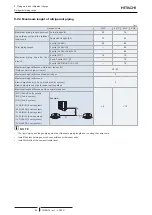
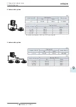
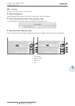
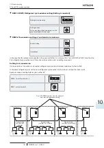
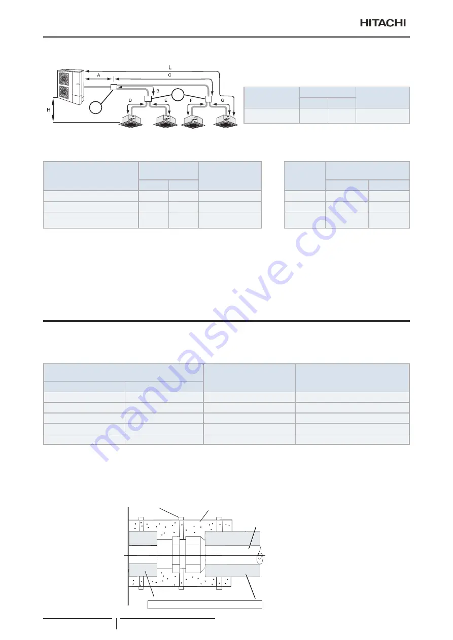
4 indoor units system
1
2
1
2
3
4
(mm)
Outdoor Unit HP
Pipe Size (A)
Branch pipe
Gas
Liquid
4 / 5 / 6
Ø15.88
Ø9.52
E-102SN4
(mm)
Total Indoor Unit capacity after
branch pipe 1+2 or 3+4
Pipe Size (B, C)
Branch line
Indoor Unit
capacity
Pipe Size (D, E, F, G)
Gas
Liquid
Gas
Liquid
≤ 1.5 HP
Ø12.70
Ø6.35
E-102SN4
≤ 1.5 HP
Ø12.70
Ø6.35
from 1.8 to 2.0 HP
Ø15.88
Ø6.35
E-102SN4
1.8/2.0HP
Ø15.88
Ø6.35
≥ 2.3 HP
Ø15.88
Ø9.52
E-102SN4
≥ 2.3 HP
Ø15.88
Ø9.52
?
N O T E
Recomended capacity ratio for 4 indoor units system:
Capacity indoor unit 1+2 / Capacity 1+2+3+4 < 60%
Capacity indoor unit 3+4 / Capacity 1+2+3+4 < 60%
If the capacity ratio of branch of indoor units 1 and 2 is bigger than 60 % of total capacity of the system or capacity ratio of branch of
indoor unit 3 and 4 is bigger than 60 % of total capacity of the system, please contact with your Hitachi Dealer or Hitachi Customer Service
Department.
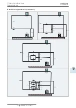
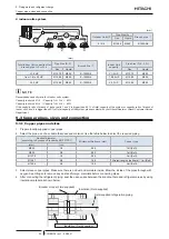
9.3 Copper pipes, sizes and connection
9.3.1 Copper pipes and sizes
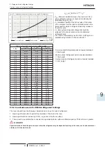
1 Prepare locally-supplied copper pipes.
2 Select the pipe size of a suitable thickness and material. Use the table below to select the required piping.
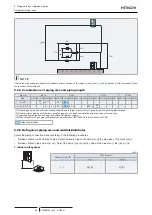
Nominal diameter
(according to European Standards EN-12735-1)
Minimum thickness (mm)
Copper type
(mm)
(in.)
Ø6.35
1/4
0.80
Coil (Soft)
Ø9.52
3/8
0.80
Coil (Soft)
Ø12.70
1/2
0.80
Coil (Soft)
Ø15.87
5/8
1.00
Straight lengths (half hard) / Coil (Soft)
Ø19.05
3/4
1.00
Coil (Soft)
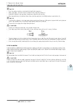
3 Select clean copper pipes. Make sure there is no dust and moisture inside. Blow the inside of the pipes through with
oxygen-free nitrogen to remove any dust and foreign materials before connecting pipes.
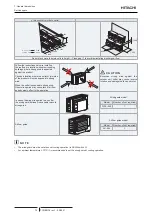
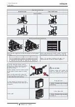
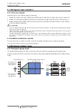
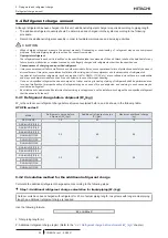
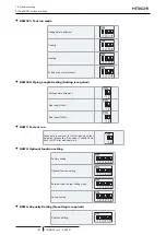
4 After connecting the refrigerant piping, seal the open space between the knockout hole and refrigerant pipes by using
insulation material as shown below:
Insulation (Field supplied)
Insulation (Field supplied).
Field-supplied refrigeration piping
Bracket or tape (Field supplied)


