background image

10  Electrical wiring

General information

TCGB0136 rev.1 - 05/2021

98

10.1  General information

!

D A N G E R

•  Do not connect or adjust any wiring or connections unless the main power switch is OFF. Check and test to ensure that if 

there is more than one source of power supply, all are turned OFF.

•  Use an earth leakage breaker with medium sensitivity, and an activation speed of 0.1 sec or less. If this is not fitted, there is 

a risk of electric shock and/or fire.

•  Install an earth leakage breaker, fuse or circuit breaker of the specific capacity for each outdoor unit power line. Not fitting 

it may cause an electric shock or fire.

•  Check that the earth wire is securely connected, tagged and locked in accordance with national and local codes.
•  Never connect the earth cable to the refrigerant pipes. The gas in the pipes could cause a fire.
•  Do not connect the earth cable to the lighting arrest system. The electrical potential of earth would increase abnormally.

!

C A U T I O N

•  Before any work to the electrical wiring or regular inspections, switch off the mains power supply of the indoor and outdoor units. Wait 

three minutes before starting installation or maintenance work.

•  Make sure that the interior and exterior fans have come to a complete standstill before starting work on the electrical wiring or regular 

inspections.

•  Protect cables, the drainage pipe, electrical components, etc. from rodents and insects; otherwise these might damage unprotected 

components and this could result in fire.

•  Do not allow cables to come into contact with the refrigerant pipes, metal edges, printed circuit boards (PCB) or the electric components 

inside the unit; the cables may be damaged and this could result in fire.

•  Firmly secure the cables inside the indoor unit with plastic flanges.
•  Connecting the operating line cables incorrectly may lead to faults in the PCB.
•  Secure the cable of the remote control switch with the cord clamp inside the electrical box.
•  Before starting work on the installation of the outdoor unit, set the DSW required to supply voltage in the correct position.

?

N O T E

•  Fix the rubber bushes with adhesive when the outdoor unit ducts are not used.
•  Use shielded twisted pair cable (more than 0.75 mm²) for operation wiring between outdoor unit and indoor unit, and operation wiring 

between indoor unit and indoor unit. (Do not use wire with more than 3 cores).

•  H-LINK twist pair shielded cable must be grounded in the outdoor unit side.
•  Use shielded wires for intermediate wiring to protect the units from noise obstacle at length of less than 300 m and size complied with 

local code.

10.1.1  Electromagnetic compatibility

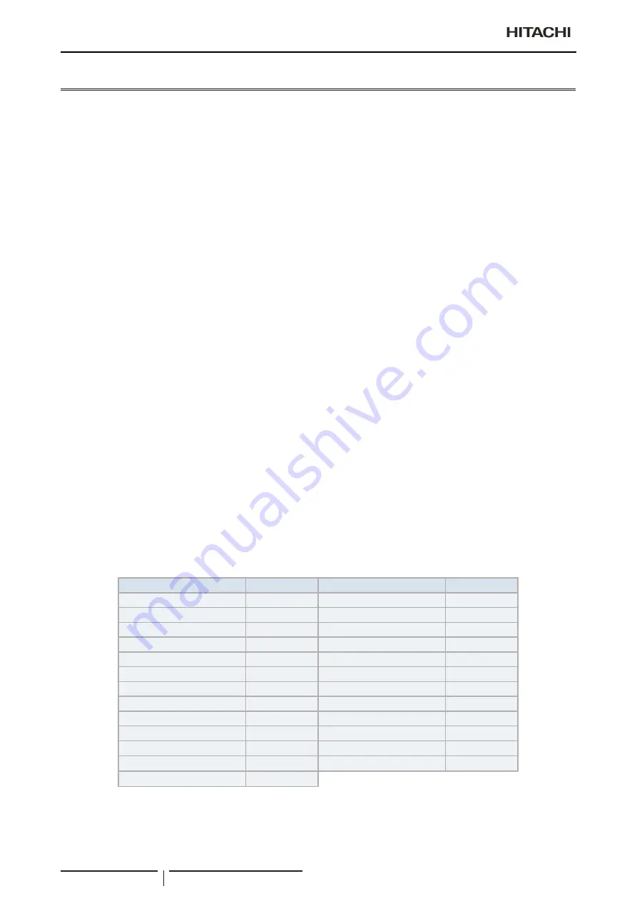
Following the Council Directive 2004/108/EC (89/336/EEC), relating to electromagnetic compatibility, next table indicates:  
Maximum permissible system impedance Z

max

 at the interface point of the user’s supply, in accordance with EN61000-3-11.

MODEL

Z

max

 (Ω)

MODEL

Z

max

 (Ω)

RAS-3HVRC2

0.43

RAS-4HRC2E

-

RAS-4HVRC2E

0.30

RAS-5HRC2E

-

RAS-5HVRC2E

0.30

RAS-6HRC2E

-

RAS-6HVRC2E

0.30

RAS-4HNC2E

-

RAS-4HVNC2E

0.30

RAS-5HNC2E

-

RAS-5HVNC2E

0.30

RAS-6HNC2E

-

RAS-6HVNC2E

0.30

RAS-4HRP2E

-

RAS-4HVRP2E

0.30

RAS-5HRP2E

-

RAS-5HVRP2E

0.30

RAS-6HRP2E

-

RAS-6HVRP2E

0.30

RAS-4HNP2E

-

RAS-4HVNP2E

0.30

RAS-5HNP2E

-

RAS-5HVNP2E

0.30

RAS-6HNP2E

-

RAS-6HVNP2E

0.30

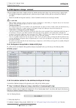
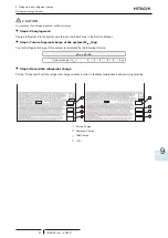
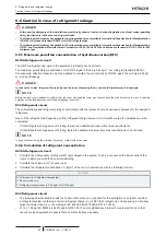
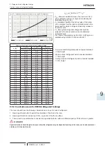
Summary of Contents for RAS-4HNC2E

Page 1: ... TECHNICAL CATALOGUE UTOPIA R32 SERIES R410A SERIES TCGB0136rev 1 05 2021 MODELS RAS 4 6 H V RC2E RAS 4 6 H V RP2E RAS 4 6 H V NC2E RAS 4 6 H V NP2E RAS 3HVRC2 ...

Page 2: ......

Page 3: ... 10 11 Co n tents General Information Features and benefits General data Capacities and selection data Acoustic characteristic curves Working range General dimensions Refrigerant cycle Piping work and refrigerant charge Electrical wiring Troubleshooting ...

Page 4: ......

Page 5: ...kit for combination with wireless remote control switch 13 1 4 12 Centralised remote controls 14 1 4 13 Building air conditioning controls 14 1 4 14 Gateways for building management systems BMS 15 1 4 15 Control support devices 16 1 4 16 Control accessories 16 2 Features and benefits 17 2 1 Features and benefits 18 2 1 1 Improvements of UTOPIA Prime UTOPIA IVX Prime Series 18 2 1 2 R32 refrigerant...

Page 6: ...eries 42 3 3 4 UTOPIA IVX Prime three phase series 42 3 4 Component data 43 3 5 Electrical data 45 3 5 1 UTOPIA series 46 4 Capacities and selection data 47 4 1 Combinability range 48 4 1 1 Connected number of indoor units 48 4 1 2 Connected capacity ratio 49 4 2 System selection procedure 50 4 2 1 Selection procedure step 1 50 4 2 2 Selection procedure step 2 52 4 3 Maximum cooling capacity 53 4 ...

Page 7: ...ce space 74 7 2 1 Basic sizes 74 7 2 2 RAS 3HVRC2 75 7 2 3 RAS 4 6 H V R N C P 2E 77 8 Refrigerant cycle 79 8 1 General notes 80 8 2 RAS 3HVRC2 80 8 3 RAS 4 6 H V R N C P 2E 81 9 Piping work and refrigerant charge 83 9 1 Refrigerant pipe selection 84 9 1 1 Pipe size selection 84 9 1 2 Multikit or distributor selection 84 9 2 Refrigerant piping range 84 9 2 1 Refrigerant piping length 84 9 2 2 Pipi...

Page 8: ... 99 10 2 General verifications 99 10 3 DIP and RSW switches settings 99 10 3 1 RAS 3HVRC2 99 10 3 2 RAS 4 6 H V R N P C 2E 102 10 4 System wiring diagram 105 10 4 1 Outdoor and indoor unit electrical wiring 105 10 4 2 Wire size 106 10 5 H LINK II system 107 10 5 1 Features 107 10 5 2 Specifications 107 10 5 3 DIP Switch setting for 2 3 and 4 indoor units systems 108 10 5 4 Examples of the system o...

Page 9: ... line up indoor units 7 1 4 6 Product line up KPI energy recovery unit 11 1 4 7 Product line up DX Interface 11 1 4 8 Product line up Econofresh 11 1 4 9 Multi Kits 12 1 4 10 Individual remote controls 12 1 4 11 Receiver kit for combination with wireless remote control switch 13 1 4 12 Centralised remote controls 14 1 4 13 Building air conditioning controls 14 1 4 14 Gateways for building manageme...

Page 10: ...he split and multisplit systems for installations where from one indoor unit single system to up to 4 indoor units are connected to the same UTOPIA outdoor unit depending on model New UTOPIA series consists in two different outdoor unit series UTOPIA Prime and UTOPIA IVX Prime which compliant with the Eco Design ErP and Energy Labelling ELD directives about seasonal energy performance ErP 206 2012...

Page 11: ...g Regulation EU Nº 517 2014 on Certain Fluorinated Greenhouse gases it is mandatory to fill in the label attached to the unit with the total amount of refrigerant charged on the installation Do not vent R32 into the atmosphere R32 is fluorinated greenhouse gas covered by the Kyoto protocol global warming potential GWP R32 675 Do not vent R410A into the atmosphere R410A are fluorinated greenhouse g...

Page 12: ...2 Classification of indoor unit models Unit type indoor unit RCI RCIM RCD RPC RPI RPK RPF RPFI Position separating hyphen fixed Capacity HP 0 4 0 6 0 8 1 0 1 5 2 0 2 5 3 0 4 0 5 0 6 0 8 0 10 0 16 0 20 0 FS SYSTEM FREE R R32 R410A refrigerant N R410A refrigerant H Hotel RPK 0 4 1 5 only 2 3 6 series P Pair E Made in Europe M Made in Malaysia Made in Japan or China f Non flammable insulation RPI 8 0...

Page 13: ...RAS 5HNC2E 7E305156 RAS 6HVRC2E 7E303036 RAS 6HRC2E 7E303136 RAS 6HVNC2E 7E305057 RAS 6HNC2E 7E305157 UTOPIA IVX Prime Individual operation models R32 R410A 1 230V 50Hz 3N 400V 50Hz 1 230V 50Hz 3N 400V 50Hz Unit Code Unit Code Unit Code Unit Code RAS 4HVRP2E 7E303234 RAS 4HRP2E 7E303334 RAS 4HVNP2E 7E305255 RAS 4HNP2E 7E305355 RAS 5HVRP2E 7E303235 RAS 5HRP2E 7E303335 RAS 5HVNP2E 7E305256 RAS 5HNP2...

Page 14: ... Half RAS 4 6 H V R N C P 2E 60291771 ASG SP11FB Full 60291782 ASG SP10BTB RAS 3HVRC2 Air inlet of rear side 60292337 ASG SP10BE RAS 4 6 H V R N C P 2E 60291938 ASG SP10LTB RAS 3HVRC2 Air inlet of left side 60292338 ASG SP10LE RAS 4 6 H V R N C P 2E 60291939 STAINLESS PLATE ASG NP335FS4 Half RAS 4 6 H V R N C P 2E Air outlet 60291940 ASG SP2 Full 60291947 ASG SP10BES2 RAS 4 6 H V R N C P 2E Air in...

Page 15: ...4104 RCI 3 0FSR 70405305 RCI 4 0FSR 70405307 RCI 5 0FSR 70405308 RCI 6 0FSR 70405309 Panel Panel P N23NA2 without Motion Sensor 70532000 P AP56NAM without Motion Sensor 70533000 P AP160KA3 Standard panel without Motion Sensor black 60279337 P AP56NAMS Motion Sensor embedded 70533100 P GP160NAP Iconic panel white 60297331 P AP56NAMR Receiver kit embedded 70533500 P GP160KAP Iconic panel black 60297...

Page 16: ...0279269 RCD 3 0FSR 60279173 RPC 3 0FSR 60279270 RCD 4 0FSR 60279174 RPC 4 0FSR 60279271 RCD 5 0FSR 60279175 RPC 5 0FSR 60279272 RCD 6 0FSR 60279176 RPC 6 0FSR 60279273 Panel Panel P AP90DNA 60297319 P AP160DNA 60297320 NOTE The RCD models must be used in combination with the indicated panels 1 indoor unit combinations with UTOPIA Prime UTOPIA IVX Prime and UTOPIA IVX Standard Premium series not al...

Page 17: ...6 0FSRE 7E426022 RPIH 6 0FSRE 7E426009 NOTE 1 Follow the detailed information about the combinability and restrictions for 0 4 HP Indoor Units which can only be used in combination with current SET FREE RAS FSXNSE RAS FSXNPE and SIDE FLOW RAS FS X NME 2 0 6 HP Indoor Units can only be used in combination with SET FREE RAS FSXNSE and RAS FSXNPE series and SIDE FLOW RAS FS X NME DUCTED INDOOR UNIT f...

Page 18: ... 60279210 RPF 2 5FSN2E 3 7E450004 RPFI 2 5FSN2E 3 7E460004 RPK 3 0FSRM 60279211 RPK 4 0FSRM 60279212 Expansion valve kit 4 EV 1 5N1 4 60921792 NOTE 1 Follow the detailed information about the combinability and restrictions for 0 4 HP Indoor Units which can only be used in combination with current SET FREE Mini RAS 4 6 FS V NME RAS 8 12 FSXNME and SET FREE RAS FSXNSE RAS FSXNPE 2 0 6 HP Indoor Unit...

Page 19: ...p DX Interface DX Interface R410A Control box Expansion valve box Unit Code EXV 2 0E2 7E611000 EXV 2 5E2 7E611001 EXV 3 0E2 7E611002 EXV 4 0E2 7E611003 EXV 5 0E2 7E611004 EXV 6 0E2 7E611005 EXV 8 0E2 7E611006 EXV 10 0E2 7E611007 1 4 8 Product line up Econofresh Econofresh R410A Unit Code EF 456N1E 7E560001 NOTE The EF 456N1E unit can only be installed in combination with the following units RPI 4 ...

Page 20: ...4202 MH 84AN1 Header Branch 70522009 1 4 10 Individual remote controls Name Description Code Figure PC ARFP1E Remote control with timer 70510003 PC ARH1E Simplified remote control 70510004 PC AWR Wireless remote control 60291969 1 General Information Product guide TCGB0136 rev 1 05 2021 12 ...

Page 21: ...Code Figure on the panel PC ALH3 RCI FSR PC AWR 60291767 PC ALHC1 RCIM FSRE PC AWR 70590906 PC ALHD1 RCD FSR PC AWR 60292053 PC ALHP1 RPC FSR PC AWR 60291823 on the wall PC ALHZ1 RPI L H FSRE EF RPI FSN 3 6 P E f RPF I FSN2E RCI FSR RCIM FSRE RCD FSR RPK FSR H M RPC FSR PC AWR 60292245 1 General Information Product guide TCGB0136 rev 1 05 2021 13 1 ...

Page 22: ... the indoor units 7E512203 CSNET Manager 2 T15 Centralised control with a touch interface of 15 inches which runs CSNET Manager 2 software to control the indoor units 7E512206 CSNET Manager 2 SL Centralised control interface screen less which runs CSNET Manager 2 software to control the indoor units 7E512204 CSNET Lite Centralised control which runs CSNET Lite software to control the indoor units ...

Page 23: ...CSNET Manager 2 and CSNET Lite Gateway Interface to KNX systems 70513303 HI AC KNX 64 Integration with installations with intelligent control BMS through CSNET Manager 2 and CSNET Lite Gateway Interface to KNX systems 70513304 HARC BX E A Integration with installation with intelligent control Building Management System Gateway Interface to LONWORKS systems H LINK I communication Max 64 units with ...

Page 24: ...ted support for both CSNET Manager 2 T10 T15 7E512302 Stand support Stand mounted support for both CSNET Manager 2 T10 T15 7E512301 Din rail Standard din rail for CSNET Lite 7E512303 PCC 1A Optional function connector 70590901 PRC 10E1 2P Extension cord 10 metres 7E790211 PRC 15E1 2P Extension cord 15 metres 7E790212 PRC 20E1 2P Extension cord 20 metres 7E790213 PRC 30E1 2P Extension cord 30 metre...

Page 25: ...sses and energy label Lot 10 20 2 3 General features and benefits of the UTOPIA Prime UTOPIA IVX Prime Series 22 2 3 1 Main features 22 2 4 Selection benefits 24 2 4 1 Wide range of UTOPIA outdoor units 24 2 4 2 Wide range of indoor units combinable with UTOPIA Prime and UTOPIA IVX Prime 25 2 5 Installation benefits 26 2 6 Start up benefits 27 2 6 1 Automatic start up test 27 2 6 2 Service verific...

Page 26: ...ictions than in previous series 8 Better efficiency than the previous series 2 1 2 R32 refrigerant R32 refrigerant has many benefits over R410A refrigerant Although both are fluorinated greenhouse gases covered by the Kyoto protocol R32 has a much lower global warming potential GWP 675 vs R410A GWP 2088 This means that it has a lower TnCO2 equivalence as a much lower charge is required to obtain b...

Page 27: ... 1rst January 2013 was Lot 10 It does concern all air conditioning systems air air with a capacity lower than 12kw operating in heating and or cooling mode These regulations include air conditioning products which are a key source of energy consumption in buildings and require all manufacturers to calculate energy usage in a more realistic way moving from nominal to seasonal creating a more accura...

Page 28: ...he System Free range of indoor units Hitachi s UTOPIA technology has all the benefits of VRF including individual control of each indoor unit with an increased number of indoor unit combinations in addition to delivering excellent part load efficiency With cooling capacities and heating capacities from 2HP to 12HP a maximum of 4 indoor units are connectable to a single outdoor unit with individual...

Page 29: ...EER Seasonal Energy Efficiency value in cooling mode SCOP Seasonal Coefficient of performance value in heating mode Energy efficiency classes SEER in cooling mode Energy efficiency classes SCOP in heating mode Energy efficiency class in cooling of the unit Energy efficiency class in heating of the unit the indication for the unit model is made for all three climate zones Nominal capacity in coolin...

Page 30: ...it number of connected Indoor Units 90 100 1 or 2 units 90 115 1 to 4 units Minimum capacity of indoor units HP 0 8 NOTE Where the parameters of installation are close to their limit values long indoor to indoor pipe distances high outdoor to indoor height difference long pipes in general etc it is recommended to follow table for best comfort see chapter 4 1 2 Connected capacity ratio Indoor unit ...

Page 31: ...it is possible a individual thermo ON OFF control enabling control of multiple indoor units by one remote control switch The air conditioning operation is adjusted to control the room temperature as appropriate according to the different air conditioning loads required for the interior zone and the perimeter zone of each room As a result this function provides comfortable air conditioning achievin...

Page 32: ...ace Large open space Flexible combinations for Individual Operation Combination example by using Individual Operation Function These configurations are to be used with UTOPIA IVX Prime Operating line Remote control line Operating line Remote control line Flexible combinations are realized by using the remote control switches Tset1 Tset2 Tset1 Tset2 Tset3 Decreased defrosting operation time and ext...

Page 33: ...IM FSR 4 way cassette compact RCD FSR 2 way cassette RPC FSR Ceiling type RPIL FSRE Indoor ducted unit slim RPI FSRE Indoor ducted unit Medium external static pressure RPIH FSRE Indoor ducted unit High external static pressure RPI FSN6E EF Indoor ducted unit for Econofresh RPK FSR H M Wall type RPF FSN2E Floor type RPFI FSN2E Floor concealed type Constant capacity unit Unit whose capacity can be s...

Page 34: ... line with personalised parameters Up to 160 units connected together in a single H LINK II bus line It is possible to connect up to 160 indoor units and up to 64 refrigerant cycles from the SYSTEM FREE range in a single H LINK II bus line To expand the installation or increase the bus lines available simply add a new line All units are managed as one through the control systems installed Example ...

Page 35: ...units forming part of the system are identified separately for the outdoor and indoor units Outdoor units the remote control can be use to allocate the series to which the operational outdoor units belong e g single or multiple series Indoor units using the rotating DIP switch on each unit Test run from the remote control Three operations for the test run are possible from the remote control 1 Aut...

Page 36: ...rmance All of the data obtained using Hitachi Service Tools is collected in different formats and monitored in several ways The software user can configure the processing of the data to monitor the parameters of most interest in each installation and allows reporting of the logged data exporting each of its screens in different ways The data reports can be used to continuously check the correct wo...

Page 37: ...reseen conditions with the maximum performance and efficiency at all times In this situation the utmost benefit is obtained from the entire installation at minimum operation costs Any range of values tending to be outside that foreseen is an indication of a situation that must be corrected as quickly as possible The management software clearly displays situations of this type and therefore is an i...

Page 38: ......

Page 39: ...al specifications 33 3 3 Cooling and heating performance 41 3 3 1 UTOPIA Prime single phase series 41 3 3 2 UTOPIA IVX Prime single phase series 41 3 3 3 UTOPIA Prime three phase series 42 3 3 4 UTOPIA IVX Prime three phase series 42 3 4 Component data 43 3 5 Electrical data 45 3 5 1 UTOPIA series 46 ...

Page 40: ...rime and UTOPIA IVX Prime R32 R410A RAS 3HVRC2 RAS 4 6 H V R C P 2E RAS 4 6 H V N C P 2E New series RCI FSR RCIM FSRE RCD FSR RPC FSR RPIL FSRE RPI FSRE RPIH FSRE RPK FSR H M RPI 4 0FSN6E EF Previous series RCI FSN4 RCIM FSN4E RCD FSN3 RPC FSN3 RPI FSN5E RPIM FSN4E DU RPK FSN H 4M RPF FSN2E RPFI FSN2E KPI E4E KPI X4E EXV E2 NOTE For older OU series contact Hitachi CSC The minimum capacity of indoo...

Page 41: ... 1140 x 950 x 370 Net weight kg 48 84 84 84 Recommended circuit breaker A 20 25 25 25 Maximum current A 15 8 22 5 22 5 22 5 Running current cooling A 7 6 12 4 16 3 21 1 Running current heating A 8 1 12 8 17 0 17 6 Size of power cable according to EN 60335 1 quantity x mm2 3 x 4 0 3 x 6 0 3 x 6 0 3 x 6 0 Size of transmission cable between indoor unit and outdoor unit quantity x mm2 2 x 0 75 2 x 0 7...

Page 42: ...950 x 370 1140 x 950 x 370 Net weight kg 86 86 86 Recommended circuit breaker A 20 20 20 Maximum current A 15 15 15 Running current cooling A 4 4 5 7 7 4 Running current heating A 4 5 6 0 6 2 Size of power cable according to EN 60335 1 quantity x mm2 5 x 4 0 5 x 4 0 5 x 4 0 Size of transmission cable between indoor unit and outdoor unit quantity x mm2 2 x 0 75 2 x 0 75 2 x 0 75 Piping diameter liq...

Page 43: ... 1140 x 950 x 370 Net weight kg 84 84 84 Recommended circuit breaker A 25 25 25 Maximum current A 22 5 22 5 22 5 Running current cooling A 13 8 18 3 23 7 Running current heating A 12 6 17 0 17 6 Size of power cable according to EN 60335 1 quantity x mm2 3 x 6 0 3 x 6 0 3 x 6 0 Size of transmission cable between indoor unit and outdoor unit quantity x mm2 2 x 0 75 2 x 0 75 2 x 0 75 Piping diameter ...

Page 44: ... 370 1140 x 950 x 370 Net weight kg 86 86 86 Recommended circuit breaker A 20 20 20 Maximum current A 15 15 15 Running current cooling A 4 9 6 4 8 3 Running current heating A 4 4 6 0 6 2 Size of power cable according to EN 60335 1 quantity x mm2 5 x 4 0 5 x 4 0 5 x 4 0 Size of transmission cable between indoor unit and outdoor unit quantity x mm2 2 x 0 75 2 x 0 75 2 x 0 75 Piping diameter liquid g...

Page 45: ...0 x 370 1140 x 950 x 370 Net weight kg 84 84 84 Recommended circuit breaker A 25 25 25 Maximum current A 22 5 22 5 22 5 Running current cooling A 12 1 16 5 21 1 Running current heating A 12 6 16 4 17 6 Size of power cable according to EN 60335 1 quantity x mm2 3 x 6 0 3 x 6 0 3 x 6 0 Size of transmission cable between indoor unit and outdoor unit quantity x mm2 2 x 0 75 2 x 0 75 2 x 0 75 Piping di...

Page 46: ...x 950 x 370 1140 x 950 x 370 Net weight kg 86 86 86 Recommended circuit breaker A 20 20 20 Maximum current A 15 15 15 Running current cooling A 4 3 5 8 7 4 Running current heating A 4 4 5 8 6 2 Size of power cable according to EN 60335 1 quantity x mm2 5 x 4 0 5 x 4 0 5 x 4 0 Size of transmission cable between indoor unit and outdoor unit quantity x mm2 2 x 0 75 2 x 0 75 2 x 0 75 Piping diameter l...

Page 47: ...70 1140 x 950 x 370 Net weight kg 84 84 84 Recommended circuit breaker A 25 25 25 Maximum current A 22 5 22 5 22 5 Running current cooling A 13 6 18 5 23 7 Running current heating A 12 4 16 4 17 6 Size of power cable according to EN 60335 1 quantity x mm2 3 x 6 0 3 x 6 0 3 x 6 0 Size of transmission cable between indoor unit and outdoor unit quantity x mm2 2 x 0 75 2 x 0 75 2 x 0 75 Piping diamete...

Page 48: ... x 370 1140 x 950 x 370 Net weight kg 86 86 86 Recommended circuit breaker A 20 20 20 Maximum current A 15 15 15 Running current cooling A 4 8 6 5 8 3 Running current heating A 4 3 5 8 6 2 Size of power cable according to EN 60335 1 quantity x mm2 5 x 4 0 5 x 4 0 5 x 4 0 Size of transmission cable between indoor unit and outdoor unit quantity x mm2 2 x 0 75 2 x 0 75 2 x 0 75 Piping diameter liquid...

Page 49: ...x RPI 3 0FSRE 7 30 3 09 14 00 4 73 4 40 14 20 R410A RAS 4HVNC2E RCI 4 0FSR 6 69 3 50 A 10 00 4 40 4 30 A 8 70 RPIH 4 0FSRE 6 90 3 33 A 10 00 4 44 3 79 A 8 70 RPI 4 0FSRE 6 21 3 24 A 10 00 4 09 3 71 A 8 70 RPC 4 0FSR 5 72 3 10 A 10 00 4 18 3 53 A 8 70 RPK 4 0FSR H M 6 17 2 16 A 10 00 3 83 2 87 A 7 40 RAS 5HVNC2E RCI 5 0FSR 6 35 3 15 A 11 90 4 24 3 98 A 11 93 RPI H 5 0FSRE 6 77 3 01 A 11 90 4 34 3 5...

Page 50: ...4 0FSRE 6 60 3 33 A 10 00 4 43 3 79 A 8 70 RPI 4 0FSRE 5 96 3 24 A 10 00 4 09 3 71 A 8 70 RPC 4 0FSR 5 51 3 10 A 10 00 4 17 3 53 A 8 70 RPK 4 0FSR H M 5 92 2 16 A 10 00 3 83 2 87 A 7 40 RAS 5HNC2E RCI 5 0FSR 6 13 3 15 A 11 90 4 23 3 98 A 11 93 RPI H 5 0FSRE 6 52 3 01 A 11 90 4 34 3 52 A 11 93 RPI 5 0FSRE 5 68 2 92 A 11 90 3 93 3 42 A 11 93 RPC 5 0FSR 5 67 2 74 A 11 90 4 09 3 21 A 11 93 RAS 6HNC2E ...

Page 51: ...hanger 44 108 Fin material Aluminium Fin pitch 1 45 1 4 Maximum operating pressure MPa 4 15 Total front area m2 0 47 1 11 Number of heat exchanger per unit 1 Fan Fan type Direct drive propeller fan Fans per unit 1 Outer diameter mm 449 544 Revolutions rpm 970 822 Nominal air flow m3 min 45 80 Motor Shell Drip proof type enclosure Starting Direct current control Power W 50 200 Quantity 1 1 Insulati...

Page 52: ...e heat exchanger 108 Fin material Aluminium Fin pitch 1 4 Maximum operating pressure MPa 4 15 Total front area m2 1 11 Number of heat exchanger per unit 1 Fan Fan type Direct drive propeller fan Fans per unit 1 Outer diameter mm 544 Revolutions rpm 822 Nominal air flow m3 min 80 Motor Shell Drip proof type enclosure Starting Direct current control Power W 200 Quantity 1 Insulation class E Compress...

Page 53: ... indoor unit If the installation is already equipped with an Earth Leakage Breaker ELB ensure that its rated current is large enough to hold the current of the units outdoor and indoor unit NOTE Electric fuses can be used instead of magnetic Circuit Breakers CB In that case select fuses with similar rated values as the CB The Earth Leakage Breaker ELB mentioned on this Technical Catalogue is also ...

Page 54: ... 3 42 16 4 3 39 22 5 4 6 25 RAS 6HVRP2E 21 1 4 38 17 6 3 64 22 5 4 6 25 RAS 4HVNP2E 13 6 2 81 12 4 2 56 22 5 4 6 25 RAS 5HVNP2E 18 5 3 83 16 4 3 39 22 5 4 6 25 RAS 6HVNP2E 23 7 4 91 17 6 3 64 22 5 4 6 25 RAS 4HNC2E 400 3 50 440 360 4 9 2 86 4 4 2 60 15 6 7 20 4 40 30 RAS 5HNC2E 6 4 3 78 6 0 3 52 15 6 7 20 RAS 6HNC2E 8 3 4 91 6 2 3 64 15 6 7 20 RAS 4HRC2E 4 4 2 56 4 5 2 65 15 6 7 20 RAS 5HRC2E 5 7 ...

Page 55: ...ction procedure 50 4 2 1 Selection procedure step 1 50 4 2 2 Selection procedure step 2 52 4 3 Maximum cooling capacity 53 4 4 Maximum heating capacity 55 4 5 Correction indoor fan speed factor 57 4 5 1 Cooling 57 4 5 2 Heating 57 4 6 Piping length correction factor fLC fLH 57 4 7 Defrost Operation correction factor fD 59 4 8 Correction ratio due to humidity CR 59 4 9 Correction factor according t...

Page 56: ... 8 RAS 4H V R C P 2E 3 6 4 6 4 0 8 RAS 5H V R C P 2E 4 5 5 75 4 0 8 RAS 6H V R C P 2E 5 4 6 9 4 0 8 RAS 4H V N C P 2E 3 6 4 6 4 0 8 RAS 5H V N C P 2E 4 5 5 75 4 0 8 RAS 6H V N C P 2E 5 4 6 9 4 0 8 NOTE In case of installation in cold territories where Outdoor Temperature may fall below 5ºC or in places where Heating load is large install a number of units with a connected capacity ratio under 100 ...

Page 57: ... 3 1 5 1 8 2 0 2 3 2 5 3 0 4 0 5 0 6 0 Indoor unit with the lowest capacity HP 0 8 1 0 1 3 1 5 1 8 2 0 2 In systems where all the units belong to the 4 Way RCI FSR model the maximum allowed capacity ratio of connected indoor units is 100 and the maximum number of connectable indoor units are OU model 3 HP 4 HP 5 HP 6 HP Maximum number of IU 1 2 3 When installing RPF I 2 0FSN2E or RPF I 2 5FSN2E si...

Page 58: ... Then the UTOPIA series 6 HP outdoor unit can be selected against the 8 HP required in a typical system 25 reduction The following figure shows the capacity curve depending on the combined indoor units Capacity kW 50 100 Total horsepower of combined indoor units HP NOTE This range can be different depending the outdoor and indoor unit model i Capacity when some indoor units are off 4 2 1 Selection...

Page 59: ...ble 6 Cooling capacity correction QC due to the piping length and altitude factor The actual cooling capacity of the pre selected unit must be calculated applying the necessary correction factors QC QMC x fLC x fAL QC Actual cooling capacity of the outdoor unit kW QMC Maximum cooling capacity of the outdoor unit kW fLC Cooling piping length correction factor fAL Corrections factor according to alt...

Page 60: ...p 1 must be calculated applying the necessary correction factors QH QMH x fLH x fD x fAL QH Actual heating capacity of the outdoor unit kW QMH Maximum heating capacity of the outdoor unit kW fLH Heating piping length correction factor fD Defrost correction factor fAL Corrections factor according to altitude Calculation of fLH Referring to the diagrams for 4 6 Piping length correction factor fLC fL...

Page 61: ...4 01 30 12 7 3 95 3 21 14 3 4 08 3 51 15 4 4 05 3 81 35 12 1 4 08 2 97 14 0 4 33 3 24 14 8 4 21 3 51 40 11 5 4 25 2 71 13 0 4 40 2 96 14 0 4 36 3 21 RAS 6HVR C P 2E 25 14 0 4 02 3 47 15 3 4 04 3 78 18 1 4 41 4 11 30 13 6 4 13 3 29 14 9 4 17 3 59 15 9 4 09 3 89 35 12 5 4 13 3 04 14 0 4 38 3 20 15 2 4 23 3 60 40 11 9 4 29 2 77 13 3 4 39 3 02 14 6 4 44 3 28 NOTE IPT data considering Outdoor Unit only...

Page 62: ...3 46 35 12 5 4 65 2 69 14 0 4 91 2 85 15 2 4 77 3 19 40 11 9 4 83 2 46 13 3 4 95 2 68 14 6 5 00 2 91 NOTE IPT data considering Outdoor Unit only R410A three phase All temperatures in ºC Outdoor unit Outdoor air inlet temperature DB Indoor air inlet temperature WB ºC DB ºC 15 21 19 27 23 32 CAP max IPT EER CAP max IPT EER CAP max IPT EER RAS 4HN C P 2E 25 10 6 3 42 3 10 11 8 3 49 3 38 13 1 3 57 3 3...

Page 63: ... 11 38 4 17 11 19 4 26 11 00 4 36 10 81 4 46 10 62 4 57 0 12 92 3 70 12 86 3 75 12 74 3 86 12 62 3 97 12 45 4 08 12 26 4 18 12 07 4 29 11 88 4 40 5 14 01 3 58 13 97 3 64 13 89 3 76 13 77 3 87 13 62 3 98 13 45 4 09 13 28 4 21 13 11 4 33 10 15 48 4 05 15 47 4 12 15 45 4 27 15 35 4 41 15 23 4 55 15 07 4 68 14 91 4 82 14 75 4 97 15 17 12 4 84 17 10 4 92 17 07 5 10 17 05 5 29 16 94 5 46 16 78 5 62 16 6...

Page 64: ...0 22 4 38 10 15 4 52 10 12 4 67 10 03 4 81 10 00 4 99 9 97 5 18 9 94 5 38 10 11 95 4 66 11 92 4 74 11 87 4 90 11 79 5 05 11 74 5 22 11 72 5 42 11 70 5 63 11 68 5 86 5 13 65 4 81 13 61 4 89 13 53 5 04 13 46 5 21 13 37 5 37 13 31 5 56 13 25 5 76 13 19 5 98 0 15 84 4 79 15 79 4 87 15 69 5 02 15 60 5 18 15 49 5 34 15 40 5 52 15 31 5 71 15 22 5 91 5 18 04 4 89 18 00 4 97 17 92 5 13 17 81 5 30 17 67 5 4...

Page 65: ...speed factor The tables does not include decreasing capacity by defrosting operation Outdoor unit HP Indoor unit fan speed 3 6 High 1 00 Medium 0 98 Low 0 97 4 6 Piping length correction factor fLC fLH The correction factor is based on the equivalent piping length in meters EL and the height between outdoor and indoor units in meters H H Height between indoor unit and outdoor unit m H 0 Position o...

Page 66: ...2 80 78 RAS 6H V R N C P 2E 15 10 5 0 5 30 25 20 15 10 90 95 60 65 50 55 80 85 70 75 20 25 10 15 40 45 30 35 5 20 EL m 100 98 96 94 92 90 88 86 84 82 80 78 76 74 72 70 Heating RAS 3HVRC2 RAS 4H V R N C P 2E 20 15 10 5 0 5 30 25 20 15 10 90 60 65 50 55 80 85 70 75 20 25 10 15 40 45 30 35 5 EL m 95 96 97 98 99 100 94 93 RAS 5H V R N C P 2E 20 15 10 5 0 5 30 25 20 15 10 90 95 60 65 50 55 80 85 70 75 ...

Page 67: ...n from the cooling capacity tables The tables are calculated on the basis of a relative humidity of 50 In some situations it s possible that the temperature condition of the ambient to be conditioned specifies other different relative humidity which affect at the Dry Bulb temperature In this cases it s necessary to calculate the difference between the indoor air inlet dry bulb temperature required...

Page 68: ......

Page 69: ...5 Acoustic characteristic curves TCGB0136 rev 1 05 2021 61 5 5 Acoustic characteristic curves Index 5 1 Overall sound level 62 5 2 Sound pressure curves 63 5 3 Sound power curves 65 ...

Page 70: ...eration when installing the unit Test Conditions 1 Distance of the unit from the measuring point 1 meter from the unit s front surface 1 5 meter from floor level Overall sound level measuring position 2 Power supply a Single phase units 1 230V 50Hz b Three phase units 3N 400V 50Hz NOTE The sound data is measured in an anechoic chamber so reflected sound should be taken into consideration when inst...

Page 71: ...r continuous noise Night Shift mode Central frequency cycle per second Cooling Heating Night mode 54 52 48 dB A Cooling Heating Night mode 54 54 51 dB A RAS 5H V R N C2E RAS 6H V R N C2E Octave sound pressure level dB overall C scale Hi Heating Hi Cooling Approximate threshold of hearing for continuous noise Night Shift mode Central frequency cycle per second Octave sound pressure level dB overall...

Page 72: ... Octave sound pressure level dB overall C scale Hi Heating Hi Cooling Approximate threshold of hearing for continuous noise Night Shift mode Central frequency cycle per second Cooling Heating Night mode 54 54 51 dB A Cooling Heating Night mode 56 56 51 dB A RAS 6H V R N P2E Octave sound pressure level dB overall C scale Hi Heating Hi Cooling Approximate threshold of hearing for continuous noise Ni...

Page 73: ...d power level dB Approximate threshold of hearing for continuous noise Frequency Hz Sound power level Global 67 dB A Sound power level Global 70 dB A RAS 5H V R N C2E RAS 6H V R N C2E Octave sound power level dB Approximate threshold of hearing for continuous noise Frequency Hz Octave sound power level dB Approximate threshold of hearing for continuous noise Frequency Hz Sound power level Global 7...

Page 74: ...eshold of hearing for continuous noise Frequency Hz Octave sound power level dB Approximate threshold of hearing for continuous noise Frequency Hz Sound power level Global 70 dB A Sound power level Global 72 dB A RAS 6H V R N P2E Octave sound power level dB Approximate threshold of hearing for continuous noise Frequency Hz Sound power level Global 72 dB A ...

Page 75: ... 2021 67 6 6 Working range Index 6 1 Working range 68 6 1 1 Power supply 68 6 1 2 Temperature working range 68 6 1 3 Special DSW configuration for low ambient temperature 15ºC only for simultaneous operation mode units UTOPIA Prime 69 ...

Page 76: ...e Minimum 21 ºC DB 15 ºC WB 15 ºC DB Maximum 32 ºC DB 23 ºC WB 27 ºC DB Outdoor side air inlet temperature Minimum 15 ºC DB Simultaneous operation mode 20 ºC WB 5 C DB Individual operation mode Maximum 46 ºC DB for external static pressure 0Pa otherwise outdoor temp 43 ºC DB 18 ºC WB NOTE DB Dry Bulb WB Wet Bulb Cooling mode for UTOPIA Prime 46 5 Working range Outdoor side air inlet temperature In...

Page 77: ...ly for simultaneous operation mode units UTOPIA Prime The outdoor ambient temperature limit is extended down from 5ºC to 15ºC under this configuration Only when Mandatory setting OU Cooling mode operation DSW2 PIN 3 ON NOTE Capacity and efficiency can vary depending on ambient conditions working settings control and protections etc CAUTION Additionally the wind guard must be installed in RAS 3HVRC...

Page 78: ......

Page 79: ...s TCGB0136 rev 1 05 2021 71 7 7 General dimensions Index 7 1 Dimensions 72 7 1 1 RAS 3HVRC2 72 7 1 2 RAS 4 6 H V R N C P 2E 73 7 2 Service space 74 7 2 1 Basic sizes 74 7 2 2 RAS 3HVRC2 75 7 2 3 RAS 4 6 H V R N C P 2E 77 ...

Page 80: ...chor bolt 2 U cut hole 3 Air suction inlet 4 Punched drain hole For drain pipe 5 Attachment hole for M10 anchor bolt 2 Long hole 6 Foot part 7 Air discharge outlet 8 Pipe cover 9 Service cover 10 Terminal board for power supply and transmission Terminal screw of power supply wire M5 Terminal screw of transmission wire M4 11 Terminal screw of earth wire M5 12 Connection of refrigerant liquid pipe W...

Page 81: ...mber Description Remarks 1 Air inlet 2 Air outlet 3 Holes for power supply wiring 4 Holes for control line wiring 5 Gas piping connection 6 Liquid piping connection 7 Service panel 8 Refrigerant piping hole 9 Drain hole 10 Drain hole 11 Earth terminal wiring M5 12 Holes for fixing machine to wall A 2 U cut holes B 2 holes ...

Page 82: ...ce space TCGB0136 rev 1 05 2021 74 7 2 Service space 7 2 1 Basic sizes RAS 3HVRC2 50 200 250 100 100 200 RAS 4 6 H V R N C P 2E 600 200 50 600 300 100 Units in mm NOTE Please refer to the Service Manual for specific information ...

Page 83: ...surrounding wall exist single unit 1000 500 50 c In case that upper side obstacles exist single unit 50 100 300 50 300 100 0 L 1 2 H A 500 1 2 H L H A 1000 d In case that upper side obstacles exist serial units 200 300 0 L 1 2 H A 500 1 2 H L H A 1000 300 f In case that surrounding wall exist serial units 0 L 1 2 A 500 1 2 H L H A 1000 A L 1000 0 L 1 2 H A 200 1 2 H L H A 350 ...

Page 84: ... be exposed to strong wind When the outlet is exposed to strong wind Direct strong wind may cause lack of air flow and adversely affect to the operation CAUTION Excessive strong wind against the outdoor unit outlet may cause inverse rotation and damage the fan and motor In case of blowing strong wind to air outlet the wind guard optional is available to avoid strong wind Wind guard model Model Num...

Page 85: ... in Inlet Side Upper Side Open Single Installation Multiple Installation Two units or more Front Side Front Side Front Side Front Side Upper Side Blocked Single Installation Multiple Installation Two units or more Outlet Side Blocked Upper Side Open Single Installation Multiple Installation Two units or more ...

Page 86: ...ir bypassed Follow the instructions below to install on the rooftop or a location without surrounding buildings where strong wind is expected against the product Choose a location where the outlet or inlet side of the product will not be exposed to strong wind When the outlet is exposed to strong wind Direct strong wind may cause lack of air flow and adversely affect to the operation CAUTION Exces...

Page 87: ...8 Refrigerant cycle TCGB0136 rev 1 05 2021 79 8 8 Refrigerant cycle Index 8 1 General notes 80 8 2 RAS 3HVRC2 80 8 3 RAS 4 6 H V R N C P 2E 81 ...

Page 88: ... Part name 1 Compressor 2 Air side heat exchanger 3 Accumulator 4 Refrigerant strainer 5 Distributor 6 Silencer 7 4 way valve 8 OU electronic expansion valve 9 Refrigerant check joint 10 Stop valve for gas line 11 Stop valve for liquid line 12 High pressure switch for protection 13 Pressure switch for control 14 Ambient thermistor 15 Discharge gas thermistor 16 Pipe thermistor Refrigerant Heating ...

Page 89: ...k joint 10 High pressure switch for protection 11 Pressure sensor Hight pressure control 12 Stop valve for gas line 13 Stop valve for liquid line 14 Check valve 15 Silencer 16 Pressure switch Low pressure control 17 Liquid pipe thermistor Te 18 Discharge gas thermistor Td 19 Ambient thermistor Ta Mark ODxT Material a 19 05Dx1 2T C1220T 0 b 15 88Dx1 0T c 12 7Dx1 0T d 9 53Dx0 8T e 6 35Dx1 07T OD Out...

Page 90: ......

Page 91: ...9 2 4 Combinations of piping size and piping length 88 9 2 5 Refrigerant piping size and multikit distributor 88 9 3 Copper pipes sizes and connection 90 9 3 1 Copper pipes and sizes 90 9 3 2 Insulation 91 9 4 Refrigerant charge amount 92 9 4 1 Refrigerant charge before shipment W0 kg 92 9 4 2 Calculation method for the additional refrigerant charge 92 9 5 Caution in case of refrigerant leakage 94...

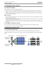
Page 92: ...it The compressor will be seriously damaged due to a lack of lubrication If smaller diameter gas refrigerant pipes are used the gas or liquid refrigerant will have serious difficulties in circulating System performance will be affected The compressor will run under more severe conditions than foreseen and will be damaged in a short space of time 9 1 2 Multikit or distributor selection Pipe connect...

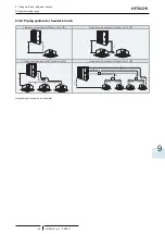
Page 93: ...ge TCGB0136 rev 1 05 2021 85 9 9 2 2 Piping system for header branch 1 indoor unit system OU from 3 to 6 HP 2 indoor units system OU from 3 to 6 HP 3 indoor units system OU from 4 to 6 HP 4 indoor units system OU from 4 to 6 HP diagrams are shown as an example ...

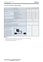
Page 94: ...fference Outdoor Indoor H Outdoor Unit is higher lower 30 20 Maximum height difference Indoor Indoor 3 Maximum height difference branch pipe indoor 2 3 and 4 indoor units system branch pipe branch pipe 4 indoor units system 3 Maximum length difference of the several branches 8 10 B C 2 and 3 unit system B D 3 unit system C D 3 unit system C G C F 4 unit system B E B D 4 unit system C G B E 4 unit ...

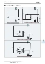
Page 95: ...rev 1 05 2021 87 9 Maximum height difference clarification 20m 30m IU1 OU1 OU1 ื ื ื ื20m ื 30m IU1 IU2 OU1 OU1 ื3m ื3m ื 3m ื ื ื ื20m ื ื ื ื 30m IU1 IU3 IU2 IU2 OU1 OU1 ื3m ื3m ื3m ื3m ื 3m ื 3m ื ื ื ื 20m ื ื ื ื 30m IU1 IU4 IU3 IU2 OU1 OU1 ื3m ื3m ื3m ื3m ื3m ื3m ื6m ...

Page 96: ... will lower cooling capacity due to larger pressure loss in gas piping and narrow operation range 2 Reducing liquid pipe size will narrow operation range due to indoor unit relation with expansion valve capacity 3 Increasing liquid pipe size will require additional refrigerant charge 4 When using Ø19 05 gas pipe soft annealed please switch ON DSW2 4 in the Outdoor Unit PCB Default combination 9 2 ...

Page 97: ...m Indoor unit capacity Pipe Size B C Gas Liquid 1 5 HP Ø12 70 Ø6 35 1 8 2 0HP Ø15 88 Ø6 35 2 3 HP Ø15 88 Ø9 52 Connections including Indoor Units 8 and 10 HP are not possible 3 indoor units system mm Outdoor Unit HP Pipe Size A Header Branch Gas Liquid 4 5 6 Ø15 88 Ø9 52 MH 84AN1 mm Indoor unit capacity Pipe Size B C D Gas Liquid 1 5 HP Ø12 70 Ø6 35 1 8 2 0HP Ø15 88 Ø6 35 2 3 HP Ø15 88 Ø9 52 ...

Page 98: ...al capacity of the system please contact with your Hitachi Dealer or Hitachi Customer Service Department 9 3 Copper pipes sizes and connection 9 3 1 Copper pipes and sizes 1 Prepare locally supplied copper pipes 2 Select the pipe size of a suitable thickness and material Use the table below to select the required piping Nominal diameter according to European Standards EN 12735 1 Minimum thickness ...

Page 99: ...t Wrong If piping installation cannot be completed until the following day or longer solder the ends of the piping to close them and load with oxygen free nitrogen using an access device such as a Schrader valve to avoid moisture and contamination by extraneous particles Do not use insulation material containing NH3 as it can damage the copper piping material and may be a source of future leakage ...

Page 100: ...ause major accidents such as fire and explosion in case of improper handling Once a non specified refrigerant has been charged no further servicing including draining of refrigerant shall be performed even in case of malfunction Improper handling of refrigerant may be a cause of fire and explosion and servicing in such cases may be considered an illegal act End clients and costumers shall be infor...

Page 101: ... the instructions in the Service Manual Step 3 Total refrigerant charge of the system WTOT kg The total refrigerant charge of this system is calculated by the following formula WTOT W0 W1 System example WTOT kg Step 4 Record the refrigerant charge Fill the F Gas Label with the refrigerant charge quantity in order to facilitate maintenance and servicing activities 4 4 Factory Charge Additional Char...

Page 102: ...untermeasures even if the gas leakage is ocurred R32 Refrigerant circuit The unit installation and refrigerant piping should comply with the relevant local and national regulations for the designed refrigerant Due to R32 refrigerant and depending on final refrigerant charge amount a minimum floor area for installation must be considered If total refrigerant charge amount 1 84kg there are no additi...

Page 103: ...ts not sealed installed 2 2m height mc kg Amin m2 Amin m2 Amin m2 Floor mounted Wall mounted Ceiling mounted 1 84 28 81 3 20 2 14 1 9 30 72 3 41 2 29 2 0 34 04 3 78 2 53 2 1 37 53 4 17 2 79 2 2 41 19 4 58 3 06 2 3 45 02 5 00 3 35 2 4 49 02 5 45 3 65 2 5 53 19 5 91 3 96 2 6 57 53 6 39 4 28 2 7 62 04 6 89 4 61 2 8 66 72 7 41 4 96 2 9 71 58 7 95 5 32 3 0 76 6 8 51 5 70 3 1 81 79 9 09 6 08 3 2 87 15 9...

Page 104: ......

Page 105: ...10 4 System wiring diagram 105 10 4 1 Outdoor and indoor unit electrical wiring 105 10 4 2 Wire size 106 10 5 H LINK II system 107 10 5 1 Features 107 10 5 2 Specifications 107 10 5 3 DIP Switch setting for 2 3 and 4 indoor units systems 108 10 5 4 Examples of the system of connection between H LINK and H LINK II units 110 10 5 5 Examples of H LINK II system 111 10 6 System Control Main concept 11...

Page 106: ... contact with the refrigerant pipes metal edges printed circuit boards PCB or the electric components inside the unit the cables may be damaged and this could result in fire Firmly secure the cables inside the indoor unit with plastic flanges Connecting the operating line cables incorrectly may lead to faults in the PCB Secure the cable of the remote control switch with the cord clamp inside the e...

Page 107: ...ating system is not able to operate correctly in the following cases When the system is supplied from the same supply line as other major consumers heavy machinery power inverter systems cranes welding machinery etc When the suppñy cables of the major consumers and the refrigeration heating system are very close together In these cases induction in the wiring to the refrigeration heating system ma...

Page 108: ... is required Setting before shipment Pipe length 5m Pipe length 30m DSW1 For test run When set pin number 1 to ON the electric current detection is cancelled Pin number 1 should be set back to OFF after electrical work DSW2 Optional function setting Factory setting Optional function setting External input output setting mode Annual cooling DSW3 Capacity Setting No setting is required Factory setti...

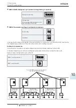
Page 109: ... only one outdoor unit is used no setting is required Setting for transmission It is required to set the outdoor unit number refrigerant cycle and end terminal resistance for the H LINK In the same refrigerant cycle set the same refrigerant cycle number for the outdoor unit and the indoor units Example incase of setting before cycle number 25 DSW4 Turn ON pin number 2 RSW1 set dial number 5 0 9 8 ...

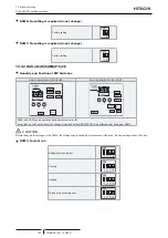
Page 110: ... DSW4 DSW2 DSW7 DSW3 DSW6 RSW1 PSW1 PSW2 PSW3 DSW1 Display 7SEG DSW5 DSW1 SEG1 DSW4 DSW2 DSW7 DSW3 RSW1 PSW1 PSW2 PSW3 DSW6 Display 7SEG DSW1 and PSW can be operated while power source is ON It may take up to 20 seconds for the change of operation state RUN STOP to be effective after having set DSW1 CAUTION Before changing the settings of the DSWs the voltage supply should be disconnected Otherwis...

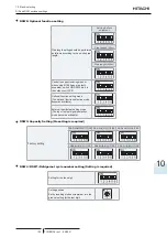
Page 111: ...or unit PCB Optional function setting mode The optional function selection mode becomes available External input output setting mode The input output signals selection mode becomes avaliable DSW3 Capacity Setting No setting is required Factory setting RAS 4HV R N C P 2E RAS 5HV R N C P 2E RAS 6HV R N C P 2E RAS 4H R H C P 2E RAS 5H R N C P 2E RAS 6H R N C P 2E DSW4 RSW1 Refrigerant cycle number se...

Page 112: ... outdoor unit number refrigerant cycle and end terminal resistance for the H LINK In the same refrigerant cycle set the same refrigerant cycle number for the outdoor unit and the indoor units Example incase of setting before cycle number 25 DSW4 Turn ON pin number 2 RSW1 set dial number 5 0 9 8 7 654 3 2 1 1 2 DSW5 1 2 DSW5 1 2 DSW5 1 2 DSW5 Turn OFF DSW5 number 1 pin for cancel of end terminal re...

Page 113: ...able more than 0 75 mm2 for operation wiring between the outdoor unit and indoor unit and operation wiring between indoor unit and indoor unit Use a 2 core wire for the operating line do not use wire with more than 3 cores Use shielded wires for intermediate wiring to protect the units from noise interference at lengths of less than 300 m The size must comply with local code Open a hole near the c...

Page 114: ...d pair cable Indoor Unit Indoor Unit Indoor Unit TB Terminal board CB Circuit Breaker field supplied ELB Earthleakage Breaker field supplied A Power source from the outdoor unit to the indoor unit ___ Field Wiring Field supplied Optional Accessory 10 4 2 Wire size Recommended minimum sizes for field provided wires Use wires which are not lighter than the ordinary polychloroprene sheathed flexible ...

Page 115: ...es is easy NOTE CSNET WEB CSNET Manager is centralized control system which allows the installation to be controlled remotely It can be connected at any point of the local corporate network or even via the Internet 10 5 2 Specifications A outdoor unit B indoor unit C refrigerant cycle D transmission cables E refrigerant piping Transmission cable 2 wire Polarity of transmission cable non polar wire...

Page 116: ...nd the impedance of the transmission circuit adapted Example of the setting of the DIP switches A B C D E F E G H F I J A Cycle number 0 B Cycle number 1 C Cycle number 2 D Terminal resistance E Number of refrigerant cycle setting for the tens digit F Number of refrigerant cycle setting for the last digit G Outdoor units H Indoor units I Address of the indoor unit setting for the tens digit J Addr...

Page 117: ...to the address of outdoor unit in the same refrigerant cycle Address of the indoor unit DSW6 RSW1 2 DSW6 RSW1 2 Setting indoor unit address Set the DSW6 and RSW1 not to overlap the setting of other indoor units in the same refrigerant cycle If no set the automatic address function is performed Name of DIP switch DIP switch and rotary switch Factory setting Indoor unit model Refrigerant cycle DSW5 ...

Page 118: ...connected 16 with indoor FSN1E units and 26 with indoor FSN4E units A Refrigerant cycle B Outdoor unit C Indoor unit D Indoor unit address E Either the current remote control switch H LINK or the new one H LINK II can be used F Only the new remote control switch H LINK II can be used NOTE The maximum number of indoor units than an H LINK II can control is 160 If you use PSC 5S and the CSNET WEB 2 ...

Page 119: ...tion for each floor A B A Outdoor units B Indoor units Connection with one main line and with the branch lines for the units A B A Outdoor units B Indoor units CAUTION The maximum number of units than can be connected is 64 outdoor units and 160 indoor units including UTOPIA and or SET FREE SET FREE Mini Do not install the wiring in a loop If the H LINK II system is not used when carrying out the ...

Page 120: ...air conditioning control If the central control device is used when carrying out electrical wiring it can be connected at any point of the H LINK II wiring A B CSNET Manager 2 A Outdoor units B Indoor units If the central control device is not used when electrical wiring is carried out you must connect the H LINK II wiring to all the systems The easiest method is usually to connect the outdoor uni...

Page 121: ...multaneously with 2 3 and 4 indoor units combinations Only one remote control switch PC ARFP1E or later models can be installed The remote control switch can control without transmission wiring up to 4 units FSN4 series or higher simultaneously All optional functions set in the remote controller switch are apply with the same setting to all indoor units Tset1 Tset1 Tset1 Tset1 Tset1 Outdoor unit R...

Page 122: ...r unit Control wiring H LINK II Tset1 Tset4 Tset3 Tset2 Tset1 Tset4 Tset3 Tset2 Individual Thermo ON OFF Operation group control only available with UTOPIA IVX Prime In the individual Thermo ON OFF control mode also known as group control all indoor units connected to the same remote controller are sharing same operation mode Tset operation mode fan speed etc Even if sharing same operating paramet...

Page 123: ... 4 Fan Speed Setting Yes 5 Timer Setting Yes 6 ON OFF by Timer Control Yes 7 Operation Indication Yes 8 Alarm Indication Yes 9 Self Checking Yes 10 Test Mode Yes 11 Individual Louver Setting Yes 2 12 Motion Sensor Setting Yes 3 NOTE Yes Available 1 Cooling and heating can not be operated simultaneously Only if all units in one group are connected to the same outdoor unit 2 Only for RCI FSR series ...

Page 124: ......

Page 125: ...11 Troubleshooting TCGB0136 rev 1 05 2021 117 11 11 Troubleshooting Index 11 1 On screen displays during abnormal operation 118 11 2 Alarm codes 120 ...

Page 126: ... unit stops due to a power shortage it will not start again even though the power comes back on Carry out the start up operations again If the power failure lasts less than 2 seconds the unit will start again automatically Electrical noise The displays can disappear from the screen and the unit can stop This is because the microcomputer has been activated to protect the unit from electrical noise ...

Page 127: ...esting for repairs Select Troubleshooting from the help menu and press OK The list of troubleshooting will be displayed OK OK 1 Select a problem from the list by pressing or and press OK The details of the selected problem will be displayed OK OK 2 Press or to scroll the text up and down OK 3 Press return The screen will return to the list of troubleshooting OK 4 Press return The screen will retur...

Page 128: ... motor overheat locking 0A Communication Abnormal communication between outdoor units Incorrect wiring broken cable loose terminals 0b Outdoor unit Incorrect outdoor unit address setting Duplication of address setting for outdoor units Sub units in same refrigerant cycle number 0C Main unit of the outdoor unit incorrectly set Two or more outdoor units set as Main Unit exist in same refrigerant cyc...

Page 129: ...g short circuit mixture of inert gas 47 Activation of the protection device from excessively low suction pressure protection from vacuum operation Shortage or leakage of refrigerant piping clogging expansion valve close locked fan motor locked 48 Abnormality of current sensor for inverter Overload operation compressor failure failure of DIP IPM heat exchanger clogged locked compressor EVI EVO fail...

Page 130: ...bnormality between the indoor and the PCB for 2 fans Transmission abnormality between the indoor unit and the PCB for 2 fans bF Abnormality in the number of connected sub PCB Abnormality in the number of connected sub PCB EE Compressor Compressor protection alarm it can not be reset from wired controller This alarm code appears when the following alarms occurs three times within 6 hours 02 07 08 3...

Page 131: ......

Page 132: ...certified with ISO 9001 of AENOR Spain for its Quality Management accordance with the standard ISO 14001 of AENOR Spain for its Environmental Management systems accordance with the standard Hitachi air conditioning products are manufactured according to ISO 9001 of JQA Japan for its Quality Management accordance with the standard ISO 14001 of JACO Japan for its Environmental Management accordance ...

Reviews: