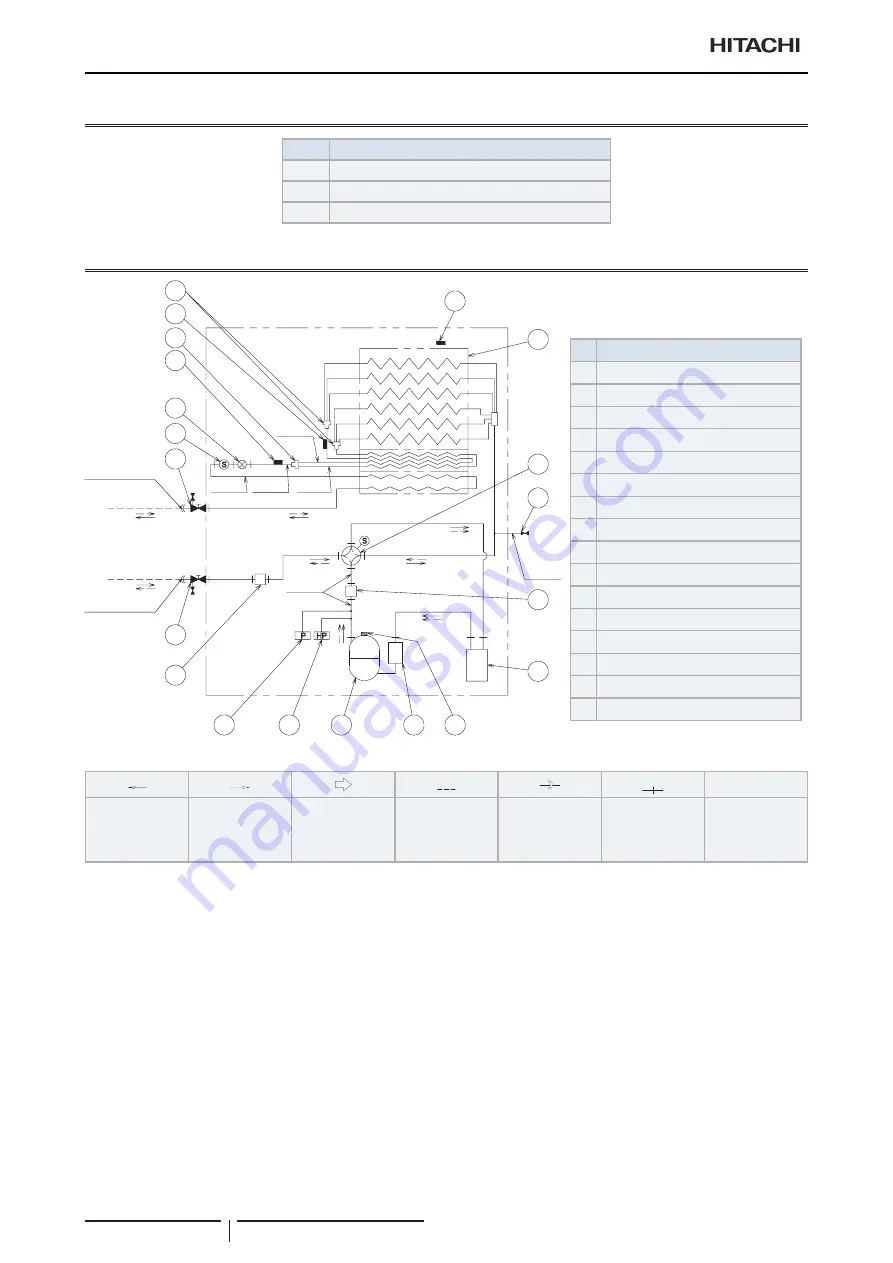
8 Refrigerant cycle
General notes
TCGB0136 rev.1 - 05/2021
80
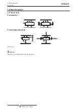
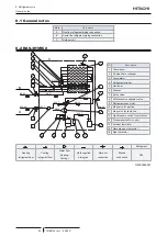
8.1 General notes
Mark
Part name
A
Gas line refrigerant piping connection
B
Liquid line refrigerant piping connection
C
Outdoor unit
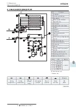
8.2 RAS-3HVRC2
6
9
7
2
3
14
16
16
3
15
1
12
13
6
10
11
4
8
5
Ø15.88
Ø9.52
Ø6.35
Ø8.0
Ø12.7
Ø9.52
Ø12.7
Ø12.7
Ø9.52
Ø12.7
Ø6.35
Ø6.35
Ø4.76
Ø6.35
5
A
B
C
Nº
Part name
1 Compressor
2 Air side heat exchanger
3 Accumulator
4 Refrigerant strainer
5 Distributor
6 Silencer
7 4-way valve
8 OU electronic expansion valve
9 Refrigerant check joint
10 Stop valve for gas line
11 Stop valve for liquid line
12 High pressure switch for protection
13 Pressure switch for control
14 Ambient thermistor
15 Discharge gas thermistor
16 Pipe thermistor
Refrigerant
Heating
refrigerant flow
Cooling
refrigerant flow
Water flow
(Heating/
Cooling)
Field supplied
piping line
Flare nut
connection
Brazed
connection
R32
G0000069481

