

9 Piping work and refrigerant charge
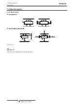
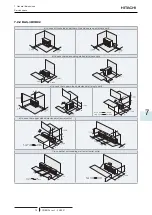
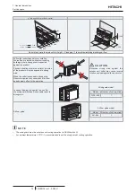
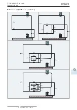
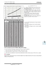
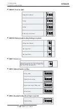
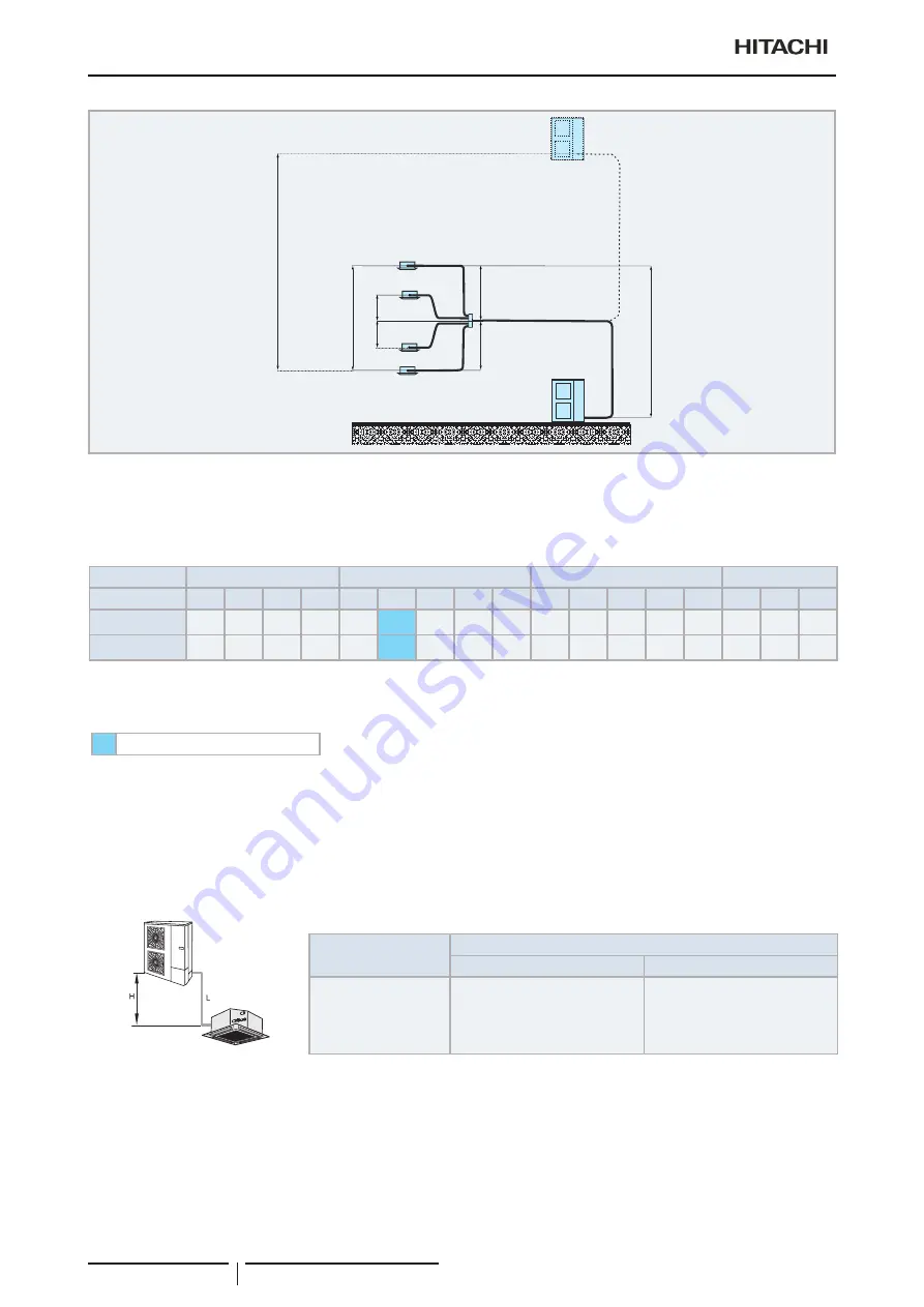
Refrigerant piping range
TCGB0136 rev.1 - 05/2021
88
ืืืื
20m
ื
30m
IU1
IU4
IU3
IU2
OU1
OU1
ื
3m
ื
3m
ื
3m
ื
3m
ื
3m
?
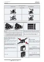
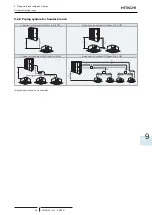
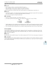
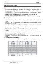
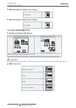
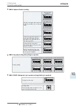
N O T E
All pictures are as example. Branch and headers are not showed as real sizes or real picture, for the installation of this components follow
the technical documentation.
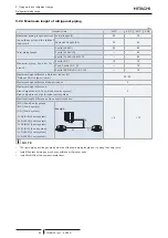
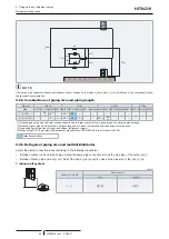
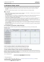
9.2.4 Combinations of piping size and piping length
Liquid
Ø6.35
Ø9.52
Ø12.70
Ø15.88
Gas
Ø9.52 Ø12.70 Ø15.88 Ø19.05 Ø12.70 Ø15.88 Ø19.05 Ø22.20 Ø25.40 Ø15.88 Ø19.05 Ø22.20 Ø25.40 Ø28.58 Ø22.20 Ø25.40 Ø28.58
3 HP
-
30
(1) (2)
30
(2)
-
30
(1)
50
-
-
-
-
-
-
-
-
-
-
-
4 - 5 - 6 HP
-
-
5
(2)
5
(2)
40
(1)
75
50
(4)
-
-
30
(3)
30
(3) (4)
-
-
-
-
-
-
(1).Reducing gas pipe size will lower cooling capacity due to larger pressure loss in gas piping and narrow operation range.
(2).Reducing liquid pipe size will narrow operation range due to indoor unit relation with expansion valve capacity.
(3).Increasing liquid pipe size will require additional refrigerant charge.
(4).When using Ø19.05 gas pipe (soft-annealed), please switch ON DSW2-4# in the Outdoor Unit PCB.
Default combination
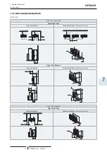
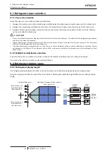
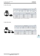
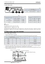
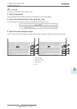
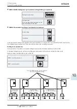
9.2.5 Refrigerant piping size and multikit/distributor
Select the piping connection sizes according to the following procedures
•
Between outdoor unit and branch pipe: Select the same pipe connection size as the pipe size of the outdoor unit.
•
Between branch pipe and indoor unit: Select the same pipe connection size as the pipe size of the indoor unit.
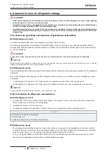
1 indoor unit system
(mm)
Outdoor Unit HP
Pipe Size (L)
Gas
Liquid
3 - 6
Ø15.88
Ø9.52


