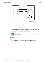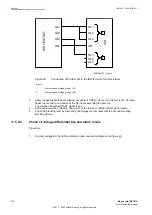
The Base values, CT and VT ratios are as follows:
2.1.
UBase
considered is 400 kV
2.2. IBase considered is 3000 A and the calculations are done considering CT
ratio as 3000 A/1 A and VT ratio as 400 kV/110 V
2.3. Rated frequency = 50 Hz
3.
Set the constant input voltage as, UL1 = 63.5
∠
0° V, UL2 = 63.5
∠
240° V, and UL3 = 63.5
∠
120°
V in secondary at rated frequency.
4.
Set the constant input current as, IL1 = 0
∠
0° A, IL2 = 0
∠
240° A, and IL3 = 0
∠
120° A in
secondary at rated frequency.
5.
Following are the steps to check the operation of
Step 1
.
Step
No.
Step1 operating characteristic verification
Expected output
5-a
Inject constant voltages of UL1 = 1.0
∠
0° V, UL2 = 1.0
∠
120° V,
UL3 = 1.0
∠
240° V and constant currents of IL1 = 0.10
∠
0° A,
IL2 = 0.10
∠
120° A, IL3 = 0.10
∠
240° A in secondary at rated
frequency.
ST1 and START signal should be
TRUE
Repeat
, to reset ST1 and START.
5-b
Inject constant voltages of UL1 = 57.73
∠
0° V, UL2 =
57.73
∠
120° V, UL3 = 57.73
∠
240° V and constant currents of
IL1 = 1.10
∠
0° A, IL2 = 1.10
∠
120° A, IL3 = 1.10
∠
240° A in
secondary at rated frequency.
ST1 and START signal should be
TRUE
Repeat
, to reset ST1 and START.
5-c
Inject constant voltages of UL1 = 76.21
∠
0° V, UL2 =
76.21
∠
120° V, UL3 = 76.21
∠
240° V and constant currents of
IL1 = 1.26
∠
0° A, IL2 = 1.26
∠
120° A, IL3 = 1.26
∠
240° A in
secondary at rated frequency.
ST1 and START signal should be
TRUE
6.
Repeat
and
for
Step 2
operation, by setting Operation2 (
Step 2
)
ON
, new
values of input currents as per slope characteristics and the
VDepFact2
based on the
I>>
value; check the output ST2 and START.
Verification of zero sequence-based operation
GUID-8EAE0867-4161-4BFF-AE89-BE44F374B6A1 v1
1.
Set the following parameters:
•
Operation
=
ON
•
Operation1
=
ON
(
Step 1
)
•
CurrentInput
=
3×ZeroSeq
•
VoltageInput
=
3×ZeroSeq
•
I >
=
125% IBase
•
VDepFact1
=
(1-117)/I> = 0.064
2.
Values of the logical signals and service values for SCCFPVOC are available on the local HMI
under:
Main menu/Tests/Function status/Unbalance protection/
CapBankCascadingFail(51V,2(I>/U<))/SCCFPVOC (51V, 2(I>/U<)):x
, where x = instance
number.
Section 11
1MRK 511 403-UEN Rev. L
Testing functionality by secondary injection
130
Bay control REC670
Commissioning manual
© 2017 - 2022 Hitachi Energy. All rights reserved
Summary of Contents for REC670
Page 1: ...Relion 670 SERIES Bay control REC670 Version 2 2 IEC Commissioning manual ...
Page 2: ......
Page 28: ...22 ...
Page 54: ...48 ...
Page 60: ...54 ...
Page 66: ...60 ...
Page 90: ...84 ...
Page 212: ...206 ...
Page 218: ...212 ...
Page 232: ...226 ...
Page 240: ...234 ...
Page 241: ...235 ...


