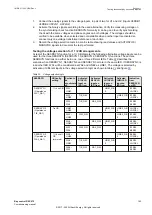
Step No.
OpMode
Changes after step 2
Expected output
3-a
Instantaneous 1
cycle or
Instantaneous 2
cycle
Change IL1 to 2 A
STL1 , STRISE, START signal should be
TRUE for 100 ms
3-b
Instantaneous 1
cycle or
Instantaneous 2
cycle
Change IL1 back to 1A
STL1 , STLOW, START signal should be
TRUE for 100 ms
3-a
RMS or DFT Mag
Change IL1 to 2 A
STL1, STRISE, START signal should be
TRUE for 100 ms
3-b
RMS or DFT Mag
Change IL1 back to 1A
STL1 , STLOW, START signal should be
TRUE for 100 ms
4.
with IL2 changes for different mode.
11.9.5.2
Completing the test
GUID-2FE5E5F0-0E6C-499E-93D2-471C183B89BF v2
Continue to test another function or end the test by changing the
TestMode
setting to
Off
. Restore
connections and settings to their original values, if they were changed for testing purposes.
11.9.6
Delta supervision of real input DELSPVC
GUID-86ADAAC5-B6D3-46FE-A090-81F7C90A31A7 v1
Prepare the IED for verification of settings outlined in Section
"Preparing the IED to verify settings"
11.9.6.1
Verifying the signals and settings
GUID-8337C76B-A361-426E-B936-763105D85588 v1
Make sure that the function is connected to any of the available real derived outputs, for example the
P output signal of the CMMXU function.
1.
Set the following parameters:
•
Operation
= ON
•
MinStVal
= 10
•
DelSt>
= 100
•
DeltaT
= 7
•
tHold
= 100
2.
Set a constant voltage input of UL1 = 63.5 V at 0° and UL2 = 63.5 V at 180° secondary and a
current signal at IL1 = 1A at 0° and IL2 = 1A at 180°.
3.
Ensure that the P output of CMMXU function has exceeded 10 MW and remains stable.
4.
Change the current signal at IL1= 2A at 0° and IL2= 2A at 180°. Both START and STARTRISE
signals should be active for 100 ms.
5.
Change the current signal at IL1= 1A at 0° and IL2= 1A at 180°. Both START and STARTLOW
signals should be active for 100 ms.
11.9.6.2
Completing the test
GUID-2FE5E5F0-0E6C-499E-93D2-471C183B89BF v2
Continue to test another function or end the test by changing the
TestMode
setting to
Off
. Restore
connections and settings to their original values, if they were changed for testing purposes.
Section 11
1MRK 511 403-UEN Rev. L
Testing functionality by secondary injection
156
Bay control REC670
Commissioning manual
© 2017 - 2022 Hitachi Energy. All rights reserved
Summary of Contents for REC670
Page 1: ...Relion 670 SERIES Bay control REC670 Version 2 2 IEC Commissioning manual ...
Page 2: ......
Page 28: ...22 ...
Page 54: ...48 ...
Page 60: ...54 ...
Page 66: ...60 ...
Page 90: ...84 ...
Page 212: ...206 ...
Page 218: ...212 ...
Page 232: ...226 ...
Page 240: ...234 ...
Page 241: ...235 ...


