11.13.1.4
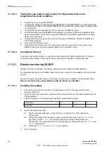
Completing the test
GUID-DD08C598-A35C-4300-9555-A0877F7DC511 v3
Continue to test another function or end the test by changing the
TestMode
setting to
Off
. Restore
connections and settings to their original values, if they were changed for testing purposes.
11.13.2
Liquid medium supervision SSIML
GUID-6426FDDA-B949-4FE7-BF42-B52014A9344B v5
Prepare the IED for verification of settings as outlined in section "
Values of logical signals for SSIML protection are available on the local HMI under
Main menu /
Test /Function status /Monitoring /InsulationLiquid /SSIML:x
, where x = 1, 2,....4.
Check that the input logical signal
BLOCK
is logical zero and that on the local HMI, the logical signals
LVLALM
,
LVLLO
,
TEMPALM
,
TEMPLO
,
ALARM
and
LOCKOUT
are logical zero.
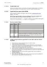
11.13.2.1
Function revision history
GUID-751C8C78-891D-423B-825A-0774D0B6C658 v2
Document
revision
Product
revision
History
A
2.2.1
-
B
2.2.1
-
C
2.2.2
-
D
2.2.3
-
E
2.2.3
-
F
2.2.4
-
G
2.2.4
Binary quality inputs SENLVLQ and SENTEMPQ have been added for pressure and
temperature sensor signals in order to control alarm and lockout signals. Whenever there
is no sensor, the quality of the binary input will be low. If sensor quality is low, then
lockout and alarm signals will get reset.
H
2.2.5
-
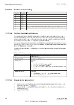
11.13.2.2
Testing the liquid medium supervision for level alarm and level lockout
conditions
GUID-C1F1E6CA-9512-4358-A4E7-84CC3698D156 v4
1.
Connect the binary inputs to consider liquid level to initiate the alarms.
2.
Activate the binary input SENLEVELQ.
3.
Consider the analogue level input SENLEVEL and set SENLEVEL to a value lower than
LevelAlmLimit
or activate binary input signal SENLVLALM, check that outputs LVLALM and
ALARM are activated after a set time delay of
tLevelAlarm
.
4.
Liquid level lockout input SENLVLLO can be used to set LVLLO.
5.
Ensure that binary input SENLEVELQ is activated and reduce the liquid level input below
LevelLOLimit
or activate the binary input signal SENLVLLO, check that LVLLO signal after a set
time delay of
tLevelLockOut
.
6.
Activate BLOCK binary input and check that the outputs LVLALM, LVLLO, ALARM and
LOCKOUT disappears.
7.
Reset the BLOCK binary input.
8.
Ensure that level lockout condition exists and then activate the reset lockout input RESETLO
and check that the outputs PRESLO and LOCKOUT reset.
1MRK 511 403-UEN Rev. L
Section 11
Testing functionality by secondary injection
Bay control REC670
191
Commissioning manual
© 2017 - 2022 Hitachi Energy. All rights reserved
Summary of Contents for REC670
Page 1: ...Relion 670 SERIES Bay control REC670 Version 2 2 IEC Commissioning manual ...
Page 2: ......
Page 28: ...22 ...
Page 54: ...48 ...
Page 60: ...54 ...
Page 66: ...60 ...
Page 90: ...84 ...
Page 212: ...206 ...
Page 218: ...212 ...
Page 232: ...226 ...
Page 240: ...234 ...
Page 241: ...235 ...


